
Crosslinked polyethylene insulated polyvinyl chloride sheath shielding power cable

A polyvinyl chloride sheath and cross-linked polyethylene technology, which is applied to power cables with shielding/conductive layers, power cables, insulated cables, etc., to achieve good anti-corrosion, good anti-interference, and improve service life.

Inactive Publication Date: 2020-12-18
吴云
View PDF7 Cites 0 Cited by
  • Summary
  • Abstract
  • Description
  • Claims
  • Application Information

AI Technical Summary

Problems solved by technology

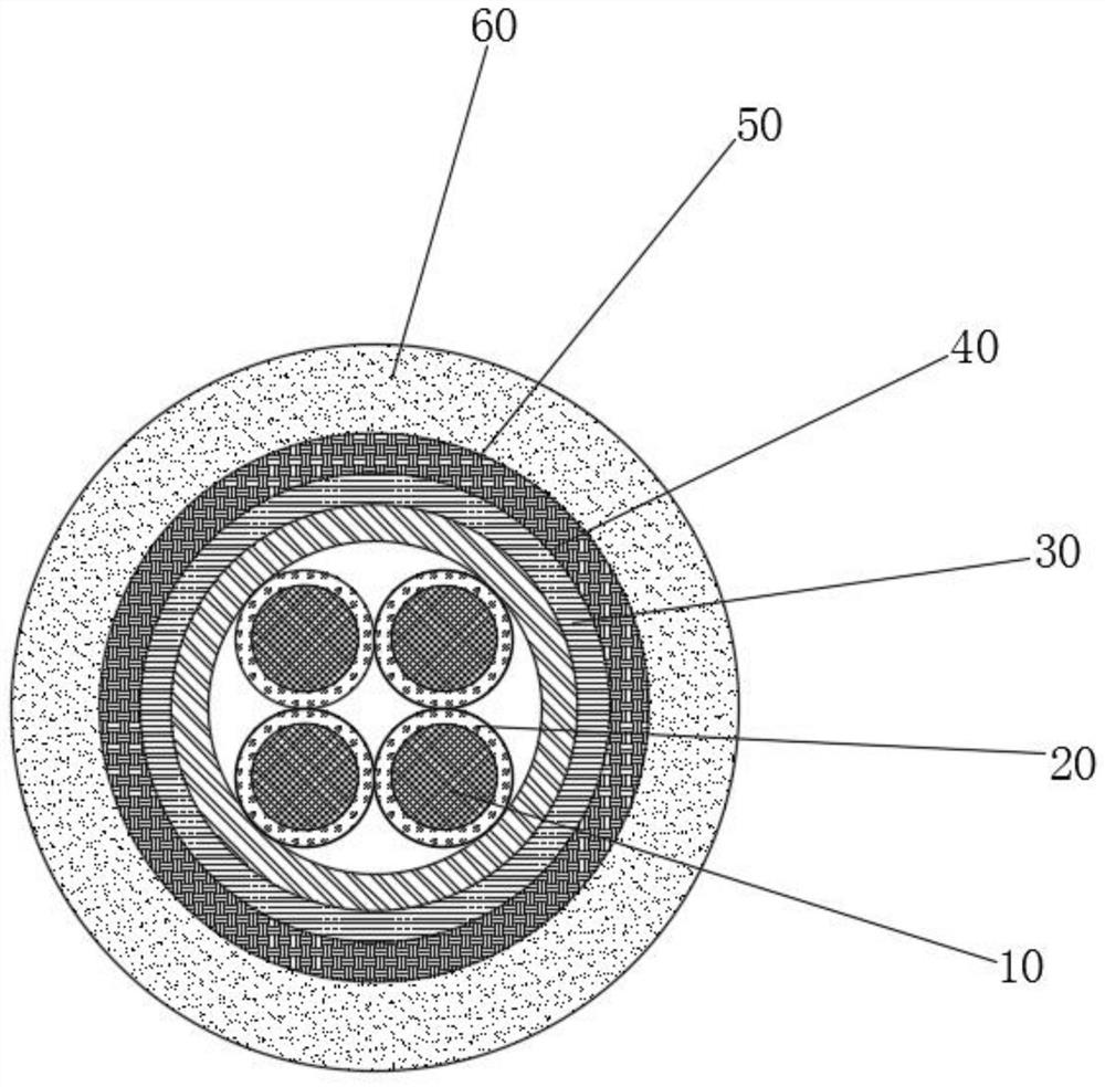
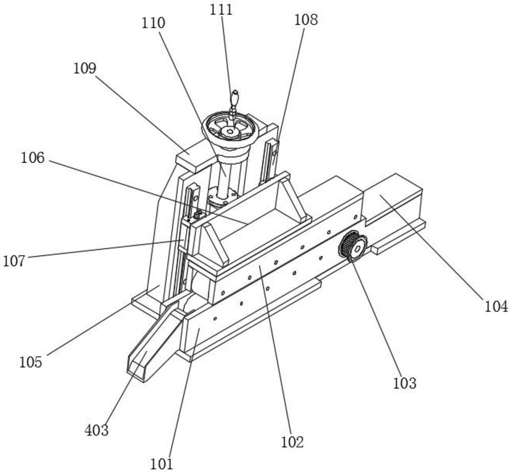
[0005] In order to overcome the above-mentioned technical problems, the object of the present invention is to provide a cross-linked polyethylene insulated polyvinyl chloride sheathed shielded power cable: (1) by covering the metal conductor with a cross-linked polyethylene insulating layer, the cross-linked polyethylene Copper wire braided shielding layer is arranged on the outside of the polyethylene insulation layer, and a galvanized steel wire armor layer is arranged on the outside of the copper wire braided shielding layer, and a ceramic fiber thermal insulation braided layer is arranged on the outside of the galvanized steel wire armor layer. The heat-insulating braided layer is covered with a PVC outer sheath, which solves the problem that the existing power cables have defects in insulation, heat insulation, safety of use and service life during use; (2) By passing one end of the conductive wire through the feeding conveying mechanism, the weaving mechanism, and the unloading conveying mechanism in sequence, turning the adjusting handwheel on the feeding conveying mechanism and the unloading conveying mechanism, passing through the threaded rod and the threaded sleeve Threaded connection drives the support frame and the second installation box down, clamps the conductive wire through the cooperation between the upper conveying roller, the lower conveying roller and the driving conveying roller, starts the conveying motor, and the conveying motor runs through the driving pulley and driven belt The driving conveying roller of the wheel rotates, thereby driving the conductive wire to be conveyed forward at a uniform speed, and the driving motor is started, and the driving motor drives the linkage shaft to rotate through the driving gear and the driven gear, thereby driving the rotating cylinder to rotate through the transmission gear and the gear collar, thus driving the The winding roller rotates around the conductive wire. During the forward conveyance of the conductive wire, the copper wire is woven on the conductive wire to form a copper wire braided shielding layer, and the galvanized steel wire is sequentially woven on the conductive wire provided with the copper wire braided shielding layer. The ceramic fiber forms the galvanized steel wire armor layer and the ceramic fiber thermal insulation braiding layer, which solves the problem that the existing power cable cannot wrap the shielding layer and other protective materials on the metal conductor well during the production process, which makes the power cable quality low and low production efficiency

Method used


Image

  • Crosslinked polyethylene insulated polyvinyl chloride sheath shielding power cable
  • Crosslinked polyethylene insulated polyvinyl chloride sheath shielding power cable
  • Crosslinked polyethylene insulated polyvinyl chloride sheath shielding power cable

Examples


Embodiment 1

[0038] see figure 1 As shown, this embodiment is a cross-linked polyethylene insulated polyvinyl chloride sheathed shielded power cable, including a conductive wire 500, a copper wire braided shielding layer 30, a galvanized steel wire armor layer 40, and a ceramic fiber heat-insulating braided layer 50 1. PVC outer sheath 60, the conductive wires 500 are made of metal conductors 10 and the cross-linked polyethylene insulating layer 20 coated on the outside of the metal conductors 10, and the four conductive wires 500 are provided with copper wire braided shielding Layer 30, filled with filling wires between the conductive wire 500 and the copper wire braided shielding layer 30, the outside of the copper wire braided shielding layer 30 is provided with a galvanized steel wire armor layer 40, and the galvanized steel wire armor layer 40 is provided with a ceramic fiber heat-insulating braid 50, and the exterior of the ceramic fiber heat-insulation braid 50 is covered with a pol...

Embodiment 2

[0040] see Figure 1-11 As shown, this embodiment is a preparation process of a cross-linked polyethylene insulated polyvinyl chloride sheathed shielded power cable, including the following steps:

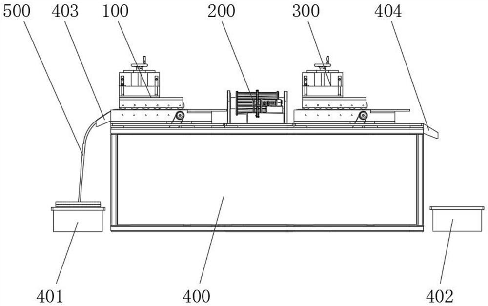
[0041] Step 1: first wrap the cross-linked polyethylene insulating layer 20 on the surface of the metal conductor 10 to obtain the conductive wire 500, wind the copper wire on the winding roller 216 of the wire braiding equipment, and connect the end of the copper wire to the conductive wire 500 After loading, install the arc-shaped plate 204 on the rotating cylinder 202 through bolts, and then pass one end of the conductive wire 500 through the feeding and conveying mechanism 100, the weaving mechanism 200, and the unloading and conveying mechanism 300 in sequence;

[0042] Step 2: Rotate the adjusting handwheel 111 on the feeding conveying mechanism 100 and the unloading conveying mechanism 300, and drive the supporting frame 106 and the second installation box 102 to descend thr...

Embodiment 3

[0048] see Figure 2-11 As shown, the wire braiding equipment in this embodiment includes a feeding conveying mechanism 100, a weaving mechanism 200, a feeding conveying mechanism 300, a mounting table 400, and a conductive wire 500, and upper and lower ends of the top of the mounting table 400 are installed respectively. The feeding conveying mechanism 100 and the unloading conveying mechanism 300, the top of the installation platform 400 is installed with the weaving mechanism 200 between the feeding conveying mechanism 100 and the unloading conveying mechanism 300, and the installation platform 400 is close to one end of the feeding conveying mechanism 100 A feeding box 401 is arranged at the bottom, and a feeding box 402 is arranged at the bottom of one end of the mounting table 400 close to the feeding conveying mechanism 300, and a feeding guide groove 403 is arranged directly above the feeding box 401, and the feeding guide Groove 403 is installed on the bottom of one e...


PUM


Abstract

The invention discloses a crosslinked polyethylene insulating polyvinyl chloride sheath shielding power cable, which is characterized in that a crosslinked polyethylene insulating layer coats outsidea metal conductor, a copper wire braided shielding layer is arranged outside the crosslinked polyethylene insulating layer, and a galvanized steel wire armor layer is arranged outside the copper wirebraided shielding layer. A ceramic fiber heat insulating braided layer is arranged outside the galvanized steel wire armor layer, and a polyvinyl chloride outer sheath wraps the ceramic fiber heat insulating braided layer. The power cable is provided with the crosslinked polyethylene insulating layer, so that the insulating performance is good, the copper wire braided shielding layer and the galvanized steel wire armor layer are arranged, so that the anti-interference effect is good, meanwhile, the tensile property of the metal conductor is improved, and the heat insulating and flame retardance of the power cable are improved by arranging the ceramic fiber heat insulating braided layer. The polyvinyl chloride outer sheath effectively protects the power cable, so that the power cable has good waterproof, oil-proof and anti-corrosion effects, and the service life of the power cable is prolonged.

Description

technical field [0001] The invention relates to the field of power cables, in particular to a cross-linked polyethylene insulated polyvinyl chloride sheathed shielded power cable. Background technique [0002] Power cables are cables used to transmit and distribute electric energy. Power cables are often used in urban underground power grids, power station lead lines, internal power supply in industrial and mining enterprises, and underwater transmission lines across rivers and seas. In power lines, the proportion of cables is gradually increasing. Power cables are cable products used to transmit and distribute high-power electric energy in the backbone lines of power systems. [0003] However, during the use of the existing power cables, there are defects in the insulation, heat insulation, safety of use and service life of the cables. Moreover, the power cables cannot be well wound and shielded on the metal conductor during the production process. layers and other protect...

Claims


Application Information

Patent Timeline
Patent Type & Authority Applications(China)
IPC IPC(8): H01B7/02H01B3/44H01B7/18H01B7/22H01B7/28H01B7/282H01B7/29H01B7/295H01B9/02H01B13/00H01B13/22H01B13/26
CPCH01B3/44H01B7/02H01B7/1875H01B7/22H01B7/228H01B7/2806H01B7/2825H01B7/292H01B7/295H01B9/021H01B9/024H01B13/00H01B13/0003H01B13/0036H01B13/22H01B13/2606
Inventor 吴云方伟李坤居盛文
Owner 吴云
Learn More