Heat exchanger capable of automatically defrosting or deicing

A heat exchanger, automatic technology, applied in the direction of indirect heat exchanger, heat exchanger type, heat exchanger shell, etc., can solve the problems of long liquefaction time, large loss of cooling capacity in transmission, etc., to improve heat exchange efficiency and improve Refrigeration efficiency, the effect of reducing manufacturing cost

Pending Publication Date: 2020-12-22
GUANGZHOU UNIVERSITY
View PDF0 Cites 1 Cited by
  • Summary
  • Abstract
  • Description
  • Claims
  • Application Information

AI Technical Summary

Problems solved by technology

However, this liquefaction time is often relatively long, which leads to a large loss of total transport cooling capacity

Method used


Image

  • Heat exchanger capable of automatically defrosting or deicing
  • Heat exchanger capable of automatically defrosting or deicing
  • Heat exchanger capable of automatically defrosting or deicing

Examples


Embodiment 1

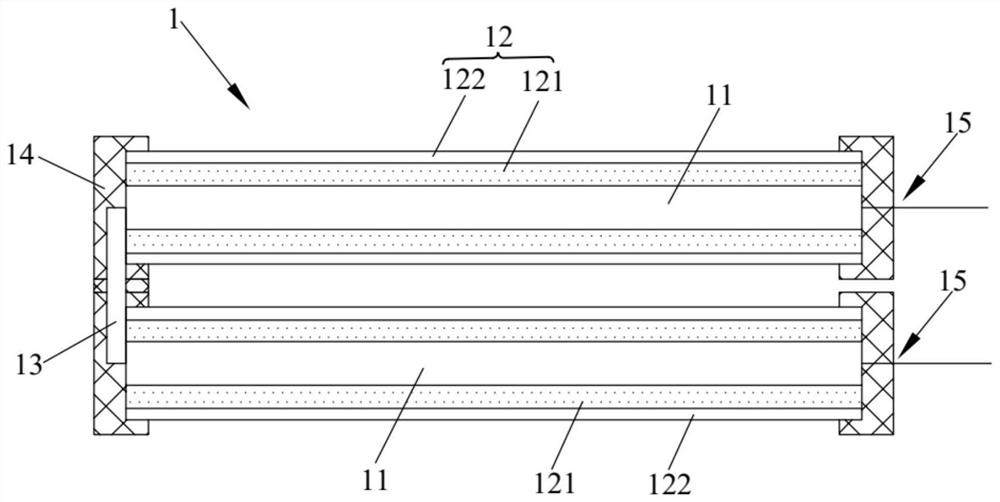
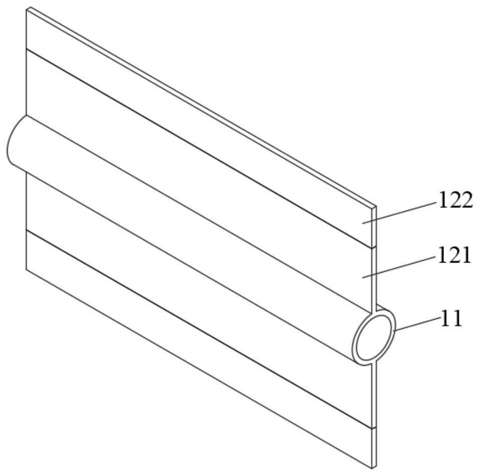
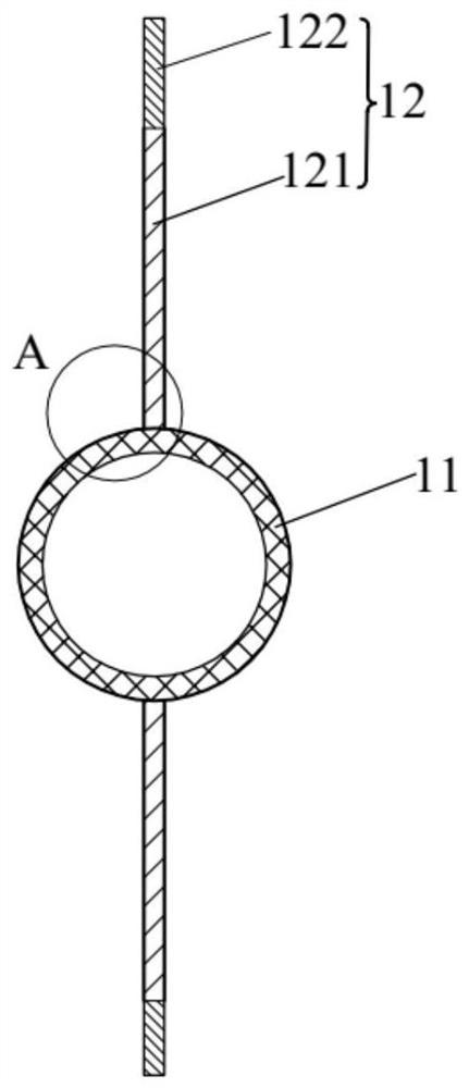
[0037] Such as Figure 1-Figure 4 As shown, this embodiment provides a heat exchanger 1 capable of automatic defrosting or deicing, including a heat exchange assembly, the heat exchange assembly includes a row pipe 11 and fins 12, and brine can be passed into the row pipe 11, The fins 12 are arranged on the outer wall of the row tube 11 , and the height of the fin 12 extends along the radial direction of the row tube 11 . The fins 12 include a first heat conduction part 121 and a second heat conduction part 122 sequentially connected to the exhaust pipe 11 , the thermal conductivity of the second heat conduction part 122 is smaller than the thermal conductivity of the first heat conduction part 121 and the heat conduction coefficient of the exhaust pipe 11 . Both the outer surface of the first heat conducting part 121 and the outer surface of the row pipe 11 are coated with a micron or nanoscale hydrophobic layer 16, and the hydrophobic layer 16 is a hydrophobic coating or a h...

Embodiment 2

[0057] For more controllable and easier removal of ice or frost layers from heat exchanger surfaces, it can be done in conjunction with a heat source. Such as Figure 5 As shown, this embodiment provides a controllable automatic defrosting or deicing heat exchanger system, which includes the heat exchanger 1 provided in Embodiment 1, and also includes a switching valve 2 and a low-temperature cold source and a high-temperature heat source 3 . The low-temperature cold source and the high-temperature heat source 3 are connected to the row pipe 11 through the switching valve 2, so as to feed brine or heat carrier into the row pipe 11. Specifically, in this embodiment, the switching valve 2 is a four-way valve. In the cooling condition, the low-temperature cooling source is connected to the exhaust pipe 11 by switching the switching valve 2, so that the brine is passed into the exhaust pipe 11; in the deicing working condition, by switching the switching valve 2, the The high-te...


PUM

PropertyMeasurementUnit
thermal conductivityaaaaaaaaaa

Abstract

The invention relates to the technical field of heat exchangers, and discloses a heat exchanger capable of automatically defrosting or deicing. The heat exchanger comprises a tube bank and fins. A refrigerating medium can be introduced into the tube bank, the fins are arranged on the outer wall of the tube bank, and the heights of the fins extend in the radial direction of the tube bank. Each fincomprises a first heat conduction part and a second heat conduction part that are sequentially connected to the tube bank, and the heat conductivity coefficient of the second heat conduction part is smaller than that of the first heat conduction part and the tube bank. The outer surface of the first heat conduction part and the outer surface of the tube bank are each coated with a micron-scale ornano-scale hydrophobic layer, and the hydrophobic layers are hydrophobic coatings or hydrophobic oil films. According to the heat exchanger capable of automatically defrosting or deicing, the heat conductivity coefficient of the second heat conduction part is relatively low, frost or ice on two sides of the tube bank can be separated under a cold release working condition, the tube bank is prevented from being annularly wrapped by the frost or ice, and meanwhile, a frost layer or an ice layer can automatically fall off under the action of gravity through the hydrophobic coatings or the hydrophobic oil films, and a heating and defrosting process can be omitted, and the cold release heat exchange efficiency of the heat exchanger is improved.

Description

technical field [0001] The invention relates to the technical field of heat exchangers, in particular to a heat exchanger capable of automatic defrosting or deicing. Background technique [0002] With the improvement of people's living standards, the demand for energy is also increasing, such as heat pump heating in winter in the north, logistics cold supply chain, etc. The transmission of cold and heat here involves the use of heat exchangers. For conventional fluid medium heat transfer, high heat transfer efficiency can be achieved by increasing the thermal conductivity of heat exchanger materials, increasing the heat transfer area, and increasing the flow velocity of conventional fluids, which can respond to the national requirements for energy saving and emission reduction . However, some heat exchanger systems involve the phase change of the medium, especially the gas-solid and liquid-solid phase changes, and these situations often become complicated. Such as an impo...

Claims


Application Information

Patent Timeline
Patent Type & Authority Applications(China)
IPC IPC(8): F25B39/02F25B47/00F28F1/20F28F19/02F28F19/04F28F9/26F28F9/00F28F21/08F28F21/06
CPCF25B39/02F25B47/00F28F1/20F28F19/02F28F19/04F28F9/26F28F9/005F28F21/081F28F21/062F25B2339/02F28F2245/04F28D2021/007F28D1/053F28F1/16F28F2215/04F28F2215/10F28F19/006F25B47/025F25D21/12
Inventor 陈奇良周孝清李峰刘燕妮杨国良何石泉
Owner GUANGZHOU UNIVERSITY
Why Eureka
Try Eureka