
Silicon carbide integrated machining system

A processing system, silicon carbide technology, applied in grain processing and other directions, can solve the problems of increasing production costs, waste of resources, reducing production efficiency, etc., and achieve the effect of saving production costs

Inactive Publication Date: 2020-12-29
洪娇娇
View PDF9 Cites 4 Cited by
  • Summary
  • Abstract
  • Description
  • Claims
  • Application Information

AI Technical Summary

Problems solved by technology

[0003] Due to the high hardness of silicon carbide, the existing crushing devices are relatively rotated by two simple crushing rollers, so that silicon carbide passes between the two for crushing, but because the existing crushing rollers are only two simple Therefore, as the crushing process proceeds, the surface of the metal crushing roller will produce many dents, which will not only affect the distance between the two crushing rollers, making the crushing force insufficient and unable to crush well, but also for After the existing simple metal crushing roller is damaged, the crushing roller can only be completely replaced, which will greatly increase the production cost and cause a waste of resources
[0004] Since the existing crushing device only crushes silicon carbide through two crushing rollers, the subsequent further crushing and grinding processes need to be carried out by other equipment, and all the crushing processes cannot be completed in one device, which increases the overall Due to the complexity of the production process and the consumption of labor, at the same time, due to the singleness of the function of the subsequent grinding device, it can only grind the demand of a single-grade particle size, so it is necessary to replace the corresponding equipment or parts to meet different needs. , which further increases the production cost and further reduces the production efficiency

Method used


Image

  • Silicon carbide integrated machining system
  • Silicon carbide integrated machining system
  • Silicon carbide integrated machining system

Examples


Embodiment Construction

[0027] The embodiments of the present invention will be described in detail below with reference to the accompanying drawings, but the present invention can be implemented in many different ways defined and covered by the claims.

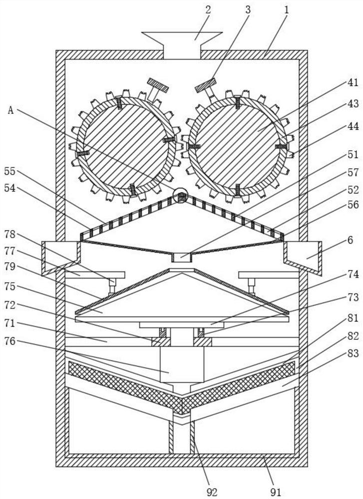
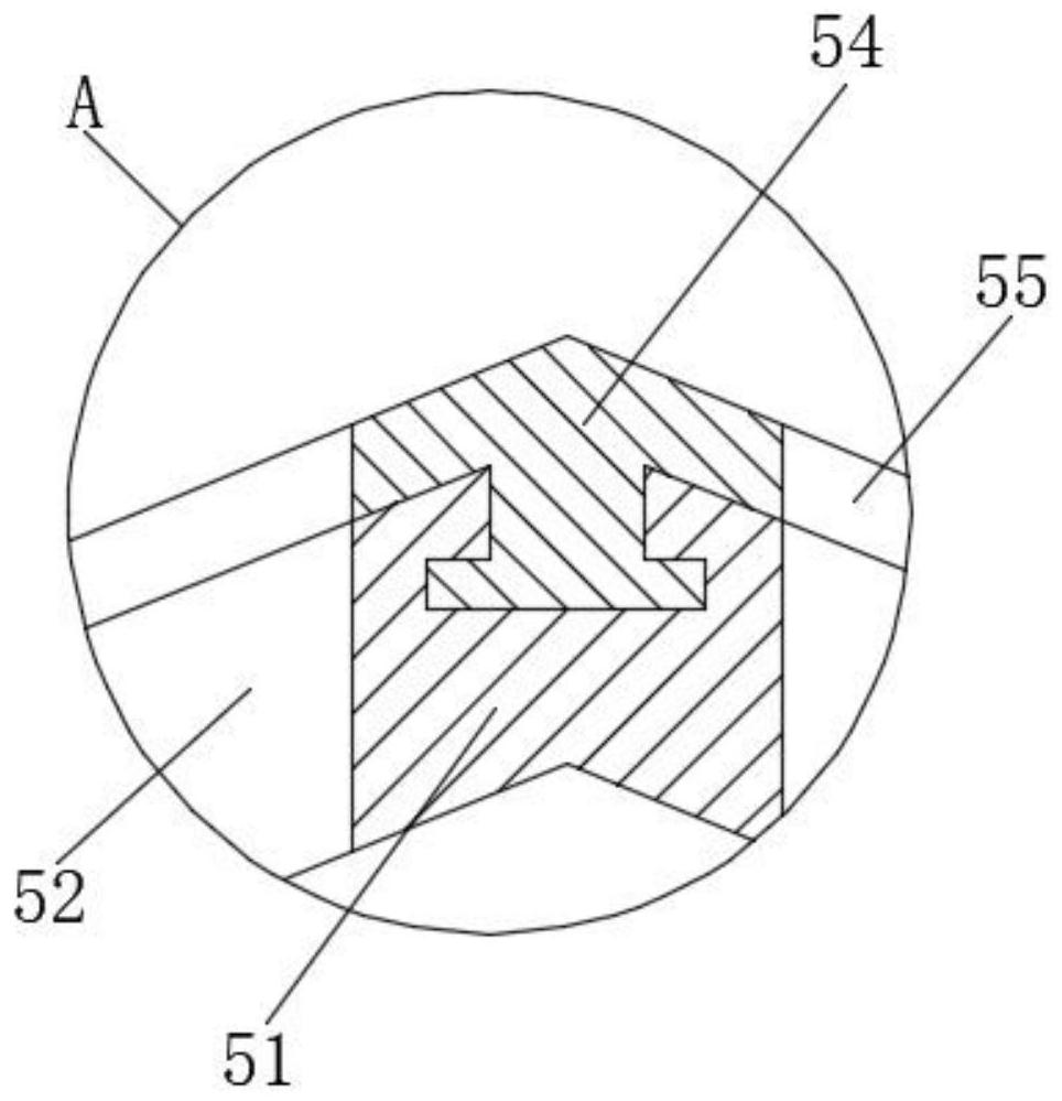
[0028] Such as Figure 1 to Figure 5As shown, a silicon carbide integrated processing system includes a housing 1, a feed hopper 2 is fixedly installed in the middle of the top of the housing 1, and two cleaning rakes 3 are fixedly fixed in the center of the upper part of the inner housing 1, and the upper part of the inner housing 1 A crushing device 4 located at the lower part of the cleaning rake 3 is mounted symmetrically in the center. The bottom of the crushing device 4 is located inside the casing 1 and a primary filter device 5 is fixedly installed on the left and right sides of the primary filter device 5. The side collection frame 6 of the wall, the bottom displacement of the first-stage filter device 5, the grinding device 7 is fixedly in...


PUM


Abstract

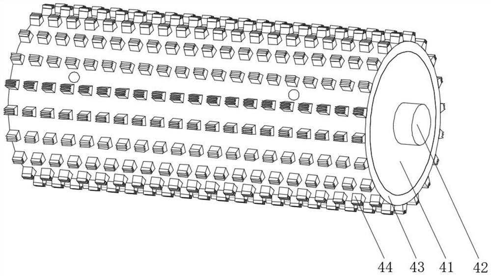
The invention relates to a silicon carbide integrated machining system which comprises a shell, a feeding hopper is fixedly installed in the middle of the top of the shell, two cleaning rakes are fixedly installed on the upper portion of the interior of the shell in a central symmetry mode, and crushing devices located on the lower portions of the cleaning rakes are movably installed on the upperportion of the interior of the shell in a central symmetry mode. A first-stage filtering device is fixedly mounted in the position, located in the shell, of the bottoms of the crushing devices, side collecting frames penetrating through the two side walls of the shell are fixedly mounted on the left side and the right side of the first-stage filtering device correspondingly, and a grinding deviceis fixedly mounted in the position, located in the shell, of the bottom of the first-stage filtering device. According to the silicon carbide integrated machining system, crushing ends are fixedly connected to the outer portions of outer rings at equal intervals in the circumferential direction, the ends of the crushing ends are in a sawtooth shape, the crushing ends on the outer rings can well extrude silicon carbide in a cutting mode through relative rotation of the outer rings, and therefore the crushing effect is better achieved.

Description

technical field [0001] The invention relates to the technical field of silicon carbide processing, in particular to an integrated silicon carbide processing system. Background technique [0002] Due to its stable chemical properties, high thermal conductivity, and good wear resistance, silicon carbide has many other uses besides being used as an abrasive. For example, silicon carbide powder is coated on a water turbine impeller or cylinder block by a special process. Internally, it can improve its wear resistance and prolong its service life. However, whether silicon carbide is artificially produced or natural silicon carbide ore, it needs to be crushed and ground into powder before use, and processes such as impurity removal and purification are carried out. , so as to meet the final production requirements, and the existing crushing device for silicon carbide has some problems in use: [0003] Due to the high hardness of silicon carbide, the existing crushing devices are ...

Claims


Application Information

Patent Timeline
IPC IPC(8): B02C21/00B02C4/08B02C4/40B02C23/10B02C2/10B02C23/14B02C4/30
CPCB02C2/10B02C4/08B02C4/30B02C4/40B02C21/00B02C23/10B02C23/14
Inventor 洪娇娇徐志强
Owner 洪娇娇
Learn More