
Narrow lap joint rolling seam welding method for high-silicon thin-specification oriented silicon steel

A technology of oriented silicon steel and welding method, which is applied in the direction of roller electrode welding, welding equipment, resistance welding equipment, etc., can solve the problems of low production efficiency, poor welding quality, high heat, etc., reduce production cost and improve weld seam quality , the effect of high promotion value

Active Publication Date: 2020-12-29
BAOSHAN IRON & STEEL CO LTD
View PDF8 Cites 1 Cited by
  • Summary
  • Abstract
  • Description
  • Claims
  • Application Information

AI Technical Summary

Problems solved by technology

[0006] Oriented silicon steel has high silicon content, the resistance of the strip steel is large, and the heat generated during the welding process is large, which will cause spatter and surface burns
At the same time, due to the thin thickness of the strip steel, the weld seam is easy to perforate, and the toughness of the deposited area near the weld seam is also poor, and the weld seam is easy to break
When welding oriented silicon steel with high-silicon thin strips under the original narrow lap seam welding machine welding process, the welding quality is poor, and it is very easy to break the strip at the weld, which seriously affects the normal stability of the unit and the production efficiency is low.

Method used


Image

  • Narrow lap joint rolling seam welding method for high-silicon thin-specification oriented silicon steel
  • Narrow lap joint rolling seam welding method for high-silicon thin-specification oriented silicon steel
  • Narrow lap joint rolling seam welding method for high-silicon thin-specification oriented silicon steel

Examples


Embodiment 1~3

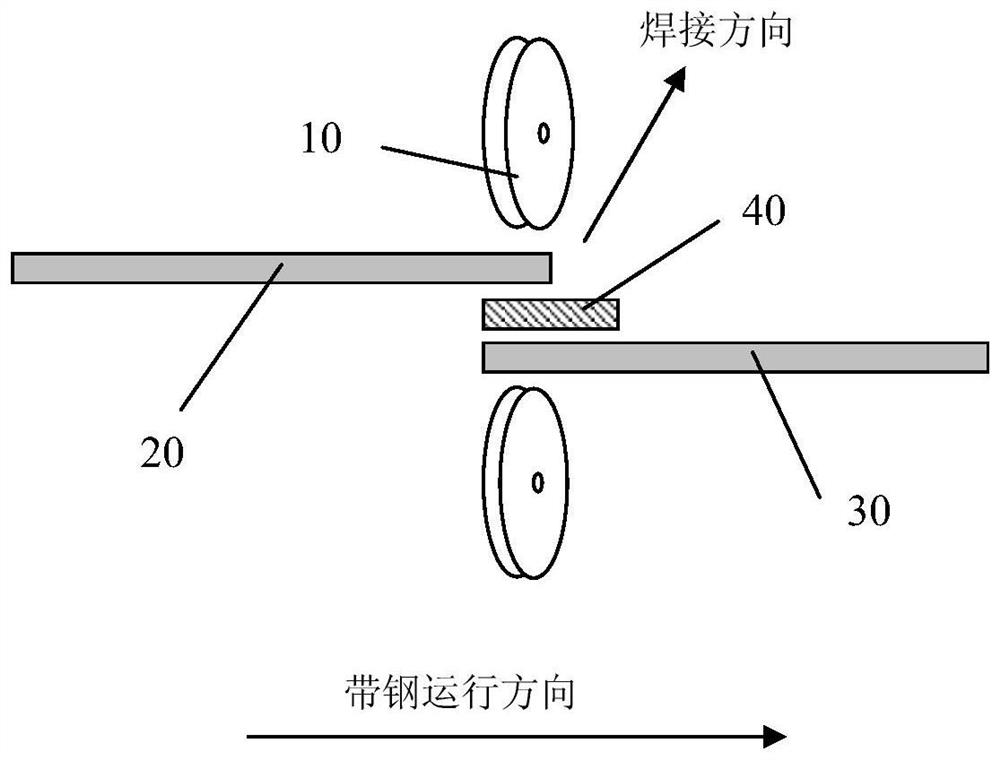
[0041]1). The front and back strips will stay at the outlet and inlet clamps of the welding machine after cutting off the bad part of the plate shape. The unevenness of the steel plate is less than 2%;

[0042]2) The front and rear strips are centered, and the deviation of the steel plate center line is less than 3mm;

[0043]3). The welding process of narrow lap rolling seam welding is carried out according to the parameters in Table 1;

[0044]4). Select compressed air to protect and cool the weld during welding.

[0045]Table 1 shows the relevant data parameters of Examples 1-3 and Comparative Examples 1-3.

[0046]The technology involved in the invention can significantly improve the welding quality of the narrow lap rolling seam welding of high-silicon thin-gauge oriented silicon steel. The front and back strip welds are well fused without warping edges; the weld surface has no perforations or cracks, and the weld has good toughness. Through the technology involved in the invention, the high-...


PUM

PropertyMeasurementUnit
Thicknessaaaaaaaaaa
Thicknessaaaaaaaaaa
Widthaaaaaaaaaa

Abstract

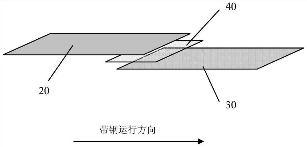
The invention discloses a narrow lap joint rolling seam welding method for high-silicon thin-specification oriented silicon steel. The method comprises the steps that S1, the tail of a forward strip steel and the head of a backward strip steel are stopped at clamps at an inlet and an outlet of a welding machine after a poor strip shape part is sheared, and the strip shape is ensured to be good; the forward strip steel and the backward strip steel are oriented silicon steel, the silicon content ranges from 3.0% to 3.5%, and the thickness ranges from 0.2 mm to 0.3 mm; S2, the forward strip steeland the backward strip steel are centered, and the deviation of the center line of the strip steel is within + / -3 mm; S3, the strip steel of a lap joint part is brushed and swept, surface oxidation films, pollutants and impurities are removed, and the brush wheel gap ranges from 0.2 mm to 0.3 mm; S4, before the forward strip steel and the backward strip steel are in lap joint, a carbon steel plate is placed between the forward strip steel and the backward strip steel, the lap joint amount of the strip steel ranges from 1 mm to 1.2 mm, the lap joint compensation amount ranges from 0.5 mm to 0.6 mm, the plate thickness ranges from 0.2 mm to 0.3 mm, and the plate width ranges from 6 mm to 9 mm; the plate comprises, by weight, 0.02% -0.07% of C, 0% -0.9% of Mn, 0.02% -0.06% of Al, 0% -0.02% of P, 0% -0.03% of Si and the balance iron; and S5, the welding current of a welding seam ranges from 8 KA to 8.5 KA, the welding pressure ranges from 6 KN to 7 KN, the welding speed ranges from 10mpmto 15mpm, and after a welding electrode melts the steel, a rolling wheel uses a rolling force of 11-15KN to press the welding seam to be flat, bright and clean along with a welding wheel.

Description

Technical field[0001]The invention relates to the technical field of welding, in particular to a narrow lap rolling seam welding method for high-silicon thin-gauge oriented silicon steel.Background technique[0002]Oriented silicon steel has high silicon content and thin strip steel, the silicon content is up to 3.5%, and the thickness is generally 0.23-0.3mm. And the higher the silicon content, the worse the toughness and plasticity of the material.[0003]The Chinese patent document with the application number 200810301407.2 discloses a process method for the head and tail flash welding of non-oriented electrical steel used in the production of a cold-rolling and pickling-rolling combined unit, which can effectively improve the quality of the weld. The process method is as follows: insert the low-carbon steel series steel with the same thickness and width as the non-oriented electrical steel between the front coil of non-oriented electrical steel and the back coil of non-oriented elec...

Claims


Application Information

Patent Timeline
IPC IPC(8): B23K11/06B23K11/34B23K11/36
CPCB23K11/06B23K11/34B23K11/36
Inventor 肖盼邹忠魁余伟
Owner BAOSHAN IRON & STEEL CO LTD
Learn More