Ultrahigh-pressure cyclone with normal inlet and automatic sand discharging system

A cyclone and ultra-high pressure technology, applied in the field of separators, can solve the problems of less separation time, low working pressure, and large energy loss, and achieve the effects of improving separation efficiency, separation accuracy, and tangential speed

Pending Publication Date: 2020-12-29
WUHAN INSTITUTE OF TECHNOLOGY +1
View PDF0 Cites 0 Cited by
  • Summary
  • Abstract
  • Description
  • Claims
  • Application Information

AI Technical Summary

Problems solved by technology

At present, the working environment of the cyclone desanding device used in the oil field is mostly in the normal pressure environment, and the working pressure is relatively low. The force is greater, and the cost of equipment materials and manufacturing is higher; at the same time, since the conventional desanding cyclone is genera

Method used


Image

  • Ultrahigh-pressure cyclone with normal inlet and automatic sand discharging system
  • Ultrahigh-pressure cyclone with normal inlet and automatic sand discharging system
  • Ultrahigh-pressure cyclone with normal inlet and automatic sand discharging system

Examples


Embodiment 1

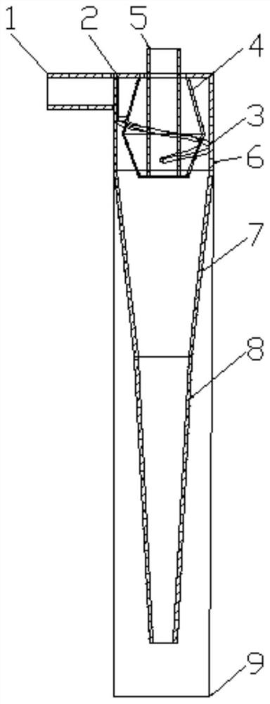
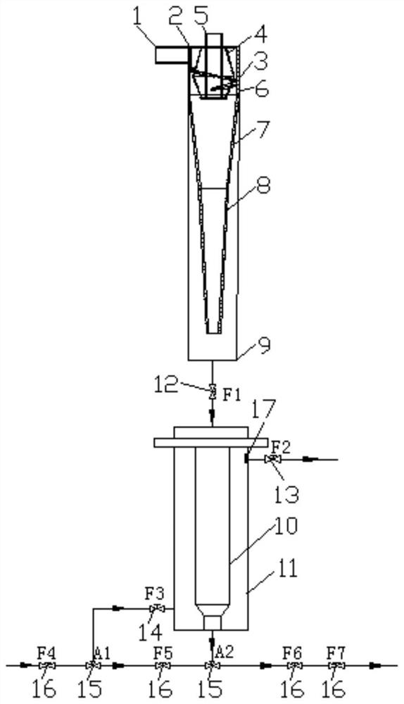
[0037] On the basis of the above-mentioned structure, in this embodiment, the upper part of the swirl tube is also vertically fixed with a speed-up tube 4, which is usually welded or bolted, and the upper and lower ends of the speed-up tube 4 can be closed. Both can be open, and the deflector 3 is located between the speed-increasing cylinder 4 and the swirl cylinder; the interior of the speed-increasing cylinder 4 is also vertically fixed with an overflow pipe 5, which is usually welded or bolted. The two ends of 5 are all exposed, and its lower end is flush with the lower end of speed-increasing tube 4, and the upper end extends vertically upwards out of the upper end of the cyclone tube. During separation, the area of ​​material circulation is reduced through the design of speed-increasing cylinder 4, thereby increasing the rate of material circulation, thereby improving the effect of material separation; the airflow generated during material circulation is discharged from t...

Embodiment 2

[0041] On the basis of Embodiment 1, in this embodiment, the speed-increasing cylinder 4 is a cylinder with thin ends and a thick spindle structure in the middle. The structure is simple and the design is reasonable, which ensures the speed of material circulation, thereby ensuring material separation. Effect.

[0042] The speed-increasing barrel 4 above can adopt a barrel with an inverted cone structure, and the structure adopts a barrel composed of an upper involute and a lower taper, so as to reduce the area of ​​material circulation, thereby increasing the rate of material circulation and ensuring material separation. Effect.

Embodiment 3

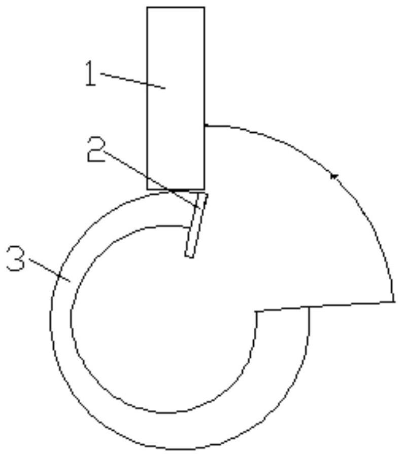
[0044] On the basis of Embodiment 1, in this embodiment, the deflector 3 is a plate body with a spiral plate structure, which is arranged on the speed-increasing cylinder 4 from top to bottom. The structure is simple, the design is reasonable, and the material circulation is prolonged. path, thereby increasing the rate of material circulation, thereby ensuring the effect of material separation.

[0045] The deflector 3 above can be an arc-shaped plate, that is, the middle part is recessed; the deflector 3 can also be a flat plate, and at this time, baffles are welded on both sides.


PUM


Abstract

The invention relates to an ultrahigh-pressure cyclone with a normal inlet and an automatic sand discharging system. The ultrahigh-pressure cyclone comprises a cyclone cylinder, an overflow port is formed in the upper end of the cyclone cylinder, and an opening is formed in the lower end of the cyclone cylinder; a feed port is formed in the upper end of the cyclone cylinder, a feed pipe and a baffle are arranged at the feed port, the feed pipe extends in the normal direction of the cyclone cylinder, and the baffle is located on one side of a discharge port of the feed pipe and used for sealingthe discharge port of the feed pipe; and a guide plate is fixedly arranged at the upper portion in the cyclone cylinder, and the guide plate is connected with the discharge port of the feed pipe. Theultrahigh-pressure cyclone has the beneficial effects that the feed port enters the cyclone in a normal direction perpendicular mode, so that the outer contour volume of the ultrahigh-pressure cyclone is effectively reduced; due to the action of the baffle and the flow guide plate, a rotational flow field is stable, the tangential speed is relatively high, and the separation efficiency is ensured; and besides, the automatic sand discharging system is arranged below the cyclone, the backflow can be eliminated, the separation efficiency is improved, and the advantages that on-line sand discharging replaces manual high-strength sand discharging, the sand discharging risk is reduced, machining is easy, and the separation efficiency is high are achieved.

Description

technical field [0001] The invention relates to the technical field of separators, in particular to an ultra-high pressure cyclone with a normal inlet and an automatic sand discharge system. Background technique [0002] In crude oil extraction operations, due to the destruction of rock structure and improper extraction methods, a certain amount of gravel is mixed in the extracted oil and gas fluid. With the continuous deepening of crude oil extraction, the problem of sand production is becoming more and more serious. Downstream pipelines will cause serious damage to ground facilities, ground gathering and transportation and processing systems, etc., affecting the normal operation of equipment. In severe cases, it will lead to shutdown of oil fields and damage to the surrounding environment, causing immeasurable losses. [0003] In the production environment of oil fields, crude oil is often in an ultra-high pressure environment, so it is necessary to perform necessary liqui...

Claims


Application Information

Patent Timeline
IPC IPC(8): E21B43/34
CPCE21B43/34
Inventor 汪威彭康林纬张思奥喻九阳郑小涛
Owner WUHAN INSTITUTE OF TECHNOLOGY
Why Eureka
Try Eureka