
Rotary kiln incineration system

A rotary kiln and kiln tail technology, applied in incinerators, rotary drum furnaces, combustion methods, etc., can solve the problems of reducing the service life of refractory castables on the surface of slag extractors, drop of castables, deformation of steel plates, etc., to reduce local The effect of abnormal temperature, reducing steel plate deformation and prolonging service life

Active Publication Date: 2020-12-29
绍兴华鑫环保科技有限公司
View PDF5 Cites 0 Cited by
  • Summary
  • Abstract
  • Description
  • Claims
  • Application Information

AI Technical Summary

Problems solved by technology

[0003] In view of the above-mentioned related technologies, the inventor believes that there are the following defects: the incineration residue has relatively high heat when it is exported from the second combustion chamber. A large amount of water vapor is evaporated, and the alternation of excessive temperature difference greatly reduces the service life of the refractory castable on the surface of the slag extractor, resulting in the drop of the castable in some areas, resulting in an abnormal rise in temperature in this area, resulting in abnormal deformation of the steel plate

Method used


Image

  • Rotary kiln incineration system
  • Rotary kiln incineration system
  • Rotary kiln incineration system

Examples


Embodiment Construction

[0061] The following is attached Figure 1-6 The application is described in further detail.

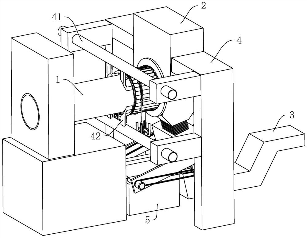
[0062] The embodiment of the present application discloses a rotary kiln 1 incineration system. refer to figure 1 , including rotary kiln 1, secondary combustion chamber 2, and slag removal machine 3. The second combustion chamber 2 is fixed on the mounting frame 4 for installing the second combustion chamber 2, and the kiln tail of the rotary kiln 1 communicates with the second combustion chamber 2, and the slag extractor 3 is located below the discharge port of the second combustion chamber 2.

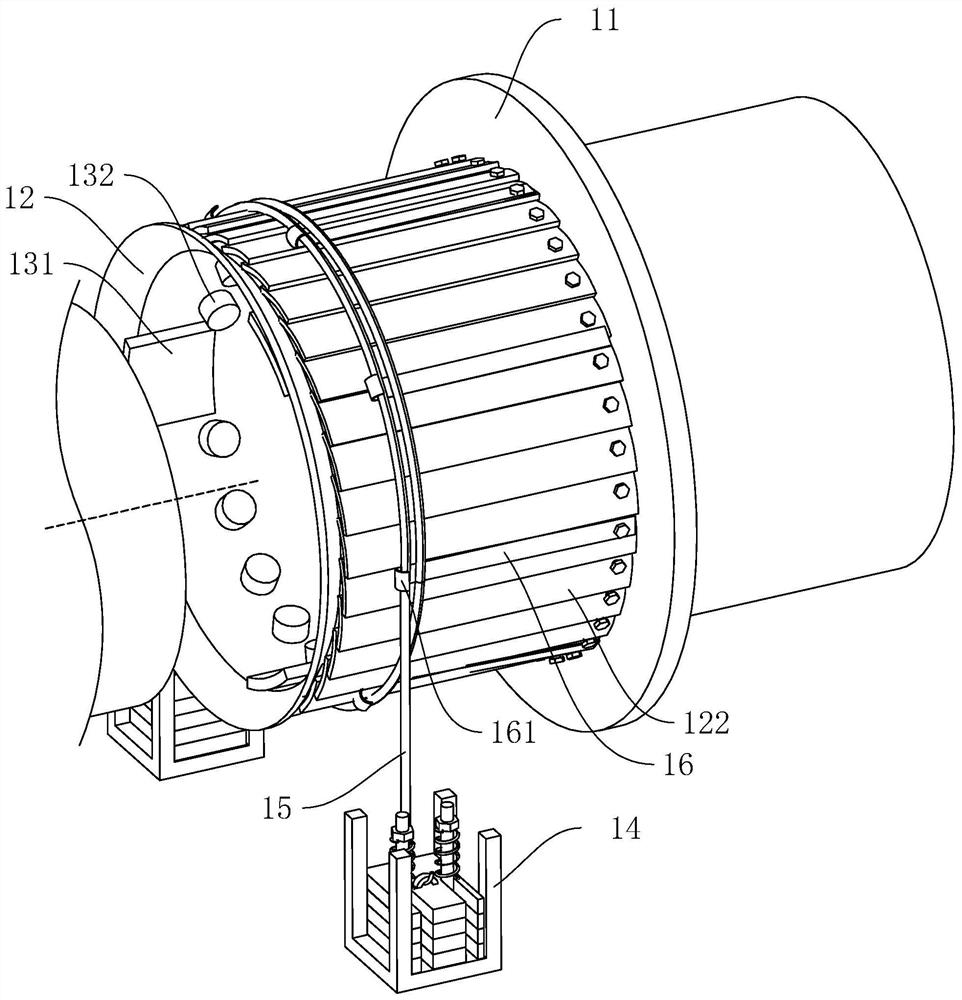
[0063] refer to figure 1 and figure 2 , The outer wall of the kiln tail of the rotary kiln 1 is provided with a cone flange 11, and the cone flange 11 is fixed on the side of the second combustion chamber 2 close to the kiln body. The sealing sleeve 12 is fixed on the end of the kiln body near the kiln tail, and the sealing sleeve 12 is rotatably connected in the cone flange 11 .

[...


PUM


Abstract

The invention relates to a rotary kiln incineration system. The system comprises a rotary kiln, a secondary combustion chamber and a slag conveyor, wherein the kiln tail of the rotary kiln communicates with the secondary combustion chamber, and the slag conveyor is located below a discharge port of the secondary combustion chamber. The system further comprises a rack, wherein a receiving box is arranged on the rack and located above the slag conveyor, a first opening and a second opening are formed in the receiving box, a stirring device is arranged in the receiving box, the stirring device comprises a stirring shaft, stirring blades, an air blowing assembly and a driving assembly, the stirring shaft is rotationally arranged in the receiving box, and the stirring blades are arranged on thestirring shaft. According to the system, the driving assembly is used for driving the stirring blades to stir incineration slag, heat and smoke of the incineration slag are sent back into the secondary combustion chamber under the action of the air blowing assembly, alternate cooling and heating with an excessively large temperature difference on the surface of the slag conveyor are reduced due to temperature drop of the incineration slag, therefore, the service life of a refractory castable on the surface of the slag conveyor is prolonged, local temperature anomalies of the slag conveyor arereduced, steel plate deformation is relieved, and the service life of the slag conveyor is prolonged.

Description

technical field [0001] The present application relates to the field of rotary kiln equipment, in particular to a rotary kiln incineration system. Background technique [0002] The rotary kiln is a horizontal cylinder lined with anti-corrosion and high temperature resistant refractory materials. The rotary kiln is composed of kiln head, body, kiln tail and transmission device. In order to keep the temperature and flue gas composition of the incinerator relatively stable, various types of wastes need to be compatible. After pretreatment and compatibility, all kinds of hazardous waste are sent into the rotary kiln body through the feeding device. Under the continuous rotation of the rotary kiln, the waste is continuously turned, heated, dried, vaporized and burned in the kiln. The combustion temperature of the rotary kiln is about 850°C. After about 60 minutes of high-temperature incineration, the materials are completely incinerated into high-temperature flue gas and inciner...

Claims


Application Information

Patent Timeline
Patent Type & Authority Applications(China)
IPC IPC(8): F23G5/14F23G5/20F23G5/44F27B7/14F27B7/24F27B7/28
CPCF23G5/14F23G5/20F23G5/44F27B7/14F27B7/24F27B7/28
Inventor 洪春强文华吴传垚李璨
Owner 绍兴华鑫环保科技有限公司
Learn More