A carbon brush lead wire and connecting bridge welding device

A welding device and connecting bridge technology, applied in welding equipment, auxiliary devices, manufacturing tools, etc., can solve problems such as low operating efficiency, lack of suitable fixtures between carbon brushes and connecting bridges, unstable welding and assembly quality, etc., and achieve improvement Operational efficiency, improvement of welding operation efficiency, and effect of improving welding quality

Active Publication Date: 2022-04-15
FUYANG DUOBAO ELECTRONICS
View PDF6 Cites 0 Cited by
  • Summary
  • Abstract
  • Description
  • Claims
  • Application Information

AI Technical Summary

Problems solved by technology

[0003] The welding between the carbon brush and the connecting bridge inside the existing carbon brush holder lacks suitable fixtures, resulting in low operating efficiency and unstable welding and assembly quality. Quality carbon brush leads with bridge soldering device
With the help of the present invention, the relative position of the carbon brush and the connecting bridge can always be kept fixed during the welding process, and the consistency of the welding process of the product can be maintained even between different processing batches. This leads to problems such as improper control of the distance between the carbon brush and the connecting bridge, distortion of the lead wire of the carbon brush, and uncertain position of the solder joint, thereby ensuring stable welding quality

Method used


Image

  • A carbon brush lead wire and connecting bridge welding device
  • A carbon brush lead wire and connecting bridge welding device
  • A carbon brush lead wire and connecting bridge welding device

Examples


Embodiment 1

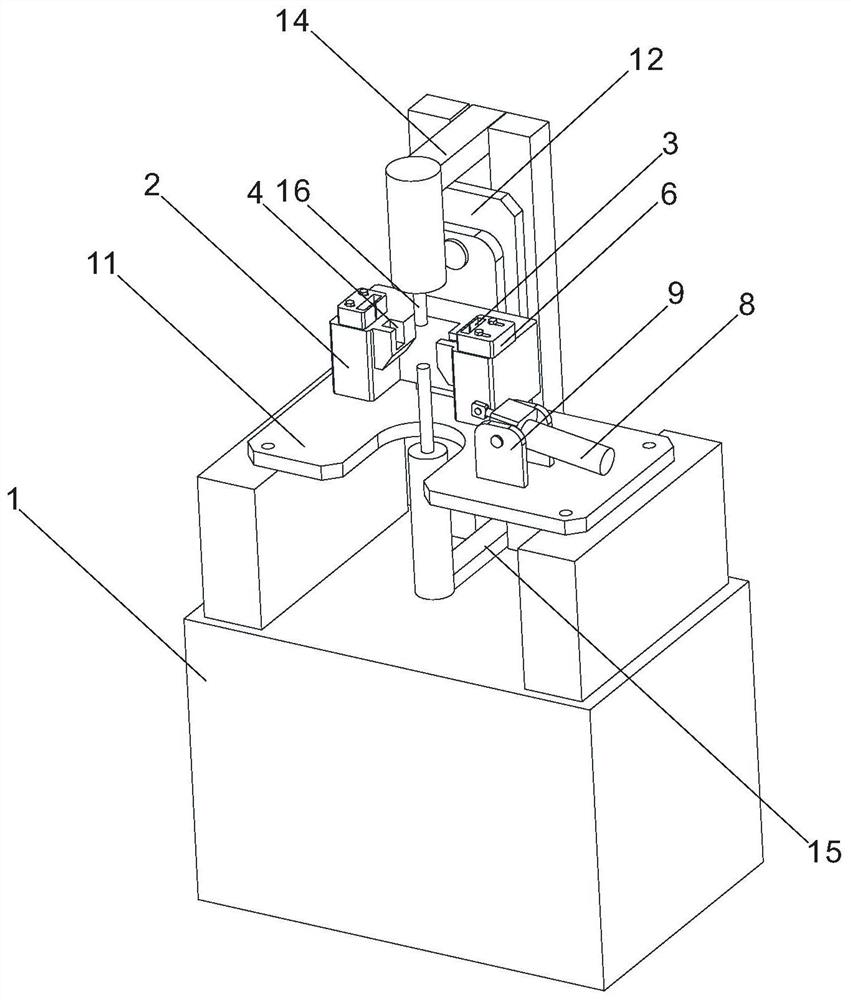
[0025] Such as image 3 , Figure 4As shown, a carbon brush lead wire and connecting bridge welding device includes a machine base 1, and also includes a welding mechanism, a welding piece positioning mechanism and a welding spot transfer mechanism. The welding mechanism, the welding piece positioning mechanism and the welding spot transferring mechanism are arranged on the machine base. 1. The welding part positioning mechanism is used to keep the relative position of the carbon brush and the connecting bridge to be welded fixed. The welding spot transfer mechanism is connected with the welding part positioning mechanism and can drive the welding part positioning mechanism to change the position so that the carbon brush lead wire and the connecting bridge are connected. Each of the to-be-welded points corresponds to the welding mechanism respectively. The weldment positioning mechanism includes a welding piece positioning seat 2, a pair of carbon brush positioning grooves 3 ...

Embodiment 2

[0028] Such as Figure 5 , Figure 6 As shown, a pendant rod support plate 17 is welded to the middle part of the top of the weldment positioning seat 2, and a horizontal transverse groove 18 is provided on the pendant pole support plate 17, and a mounting roller is arranged in the horizontal transverse groove 18, and the mounting roller A pendant bar 19 is hinged on the top, and a crimping part 20 is slidably connected on the pendant bar 19, and a back-moving spring is connected between the crimping part and the pendant bar 19. The upper welding arm 14 is fixedly provided with a left and a right two can During the descending process, the upper welding arm 14 touches the pressing bar 21 of the pressing wire member, and the pressing bar 21 is symmetrically located on both sides of the welding electrode head 16 . The crimping member 20 includes a crimping slider, a briquetting block 23 and a crimping roller 25. The hanging rod 19 is provided with an axial chute 22, and the crim...

Embodiment 3

[0031] The crimping part 20 includes a collar, a pressing block and a crimping roller. The collar is slidably sleeved on the pendant rod 19. An anti-rotation key bar is provided on the inner wall of the collar, and an axial chute is provided on the pendant rod 19. , the anti-rotation key bar is slidably embedded in the axial slide groove, the pressure block is fixedly connected to the collar, the top of the pressure block is provided with a wedge-shaped guide groove, the bottom end of the pressure rod is wedge-shaped to match the wedge-shaped guide groove, and the pressure wire roller The shaft is rotatably connected to the bottom of the pressing block. All the other are with embodiment 2.


PUM


Abstract

The invention provides a carbon brush lead wire and connecting bridge welding device, which includes a machine base, and also includes a welding mechanism, a welding piece positioning mechanism and a welding spot transfer mechanism. The welding mechanism, the welding piece positioning mechanism and the welding spot transfer mechanism are arranged on the base Above, the welding piece positioning mechanism is used to keep the relative position of the carbon brush and the connecting bridge to be welded fixed, and the welding spot transfer mechanism is connected with the welding piece positioning mechanism and can drive the welding piece positioning mechanism to change the position so that the lead wire of the carbon brush and the connecting bridge are connected. Each to-be-welded point corresponds to the welding mechanism respectively. In the present invention, the positioning mechanism of the welding part pre-determines the positions of the carbon brush and the connecting bridge. When welding, the carbon brush and the connecting bridge only need to be placed in place without further adjustment, and the welding can be completed quickly and accurately, so the working efficiency can be greatly improved. And it can improve the welding quality of components inside the carbon brush holder.

Description

technical field [0001] The invention relates to a welding tool, more specifically, it relates to a carbon brush lead wire and connecting bridge welding device. Background technique [0002] The carbon brush holder is an important part of the electrical circuit and is widely used in automatic mechanical equipment and production lines. Its function is to apply pressure to the carbon brush that is in sliding contact with the surface of the commutator or collector ring through the spring to make it fixed The current is stably conducted between the body and the rotating body. On different devices, carbon brush holders have different structural forms, such as figure 1 In the shown carbon brush holder, four carbon brushes surround the collector ring, two adjacent carbon brushes are connected in parallel on a connecting bridge and then a lead-out line is drawn out from the connecting bridge, and the two carbon brushes are connected to the connecting bridge. There are two solder jo...

Claims


Application Information

Patent Timeline
Patent Type & Authority Patents(China)
IPC IPC(8): B23K3/08B23K1/00
CPCB23K3/087B23K1/0016
Inventor 李永琴
Owner FUYANG DUOBAO ELECTRONICS
Why Eureka
Try Eureka