A method for preparing conductive bioscaffolds based on self-excited electrostatic field-driven melt-jet 3D printing

A bio-stent and 3D printing technology, applied in the field of 3D printing, can solve the problems that it is difficult to ensure the high-precision concentricity of the ring electrode and the nozzle, affect the high-precision printing and high-stable electric field requirements, and the outer wall of the extraction electrode nozzle does not fit, etc., to achieve convenient replacement , good print quality, easy to produce effects

Active Publication Date: 2022-05-27
QINGDAO TECHNOLOGICAL UNIVERSITY
View PDF7 Cites 0 Cited by
  • Summary
  • Abstract
  • Description
  • Claims
  • Application Information

AI Technical Summary

Problems solved by technology

However, this method uses a nozzle. Because the composite material is conductive, there is a problem that the entire micro-screw and the system are easily connected to the high-voltage electricity on the nozzle, which will cause a short circuit in the printing system.
[0005] ZL201710528176.8 discloses an electric field-driven spray deposition 3D printing device. This method only uses a connected ring-shaped extraction electrode to provide the required electric field, does not require a grounded counter electrode, and the ring electrode does not directly contact the nozzle. There are limitations in material jet deposition 3D printing in terms of printing materials, nozzle materials, and substrate materials, but there are still some problems. In actual use, it is difficult to ensure that the ring electrode and the nozzle are concentric with high precision, which affects the stability of the electric field during high-precision printing. , affecting the accuracy of the printed results
The applicant found that because the extraction electrode is a flat plate electrode, the center is set as a circular through hole, the wall thickness, that is, the distance between the outer diameter and the central circular hole is relatively large, and the inner diameter of the extraction electrode does not fit the outer wall of the nozzle, resulting in an electric field The focusing effect is not ideal, and the electric field strength directly under the nozzle is low, which affects the high-stable electric field requirement for high-precision printing

Method used


Image

  • A method for preparing conductive bioscaffolds based on self-excited electrostatic field-driven melt-jet 3D printing
  • A method for preparing conductive bioscaffolds based on self-excited electrostatic field-driven melt-jet 3D printing
  • A method for preparing conductive bioscaffolds based on self-excited electrostatic field-driven melt-jet 3D printing

Examples


Embodiment Construction

[0039] The accompanying drawings that form a part of the present application are used to provide further understanding of the present application, and the schematic embodiments and descriptions of the present application are used to explain the present application and do not constitute improper limitations on the present application.

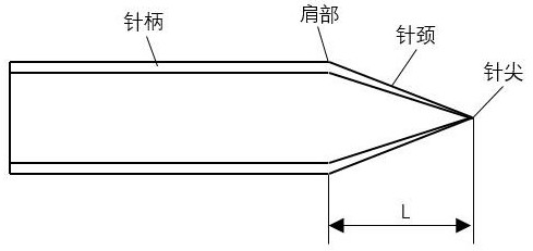
[0040] In this application, an extraction electrode is formed by attaching, winding and fixing a conductive patch on the shoulder of a glass nozzle. The conductive patch is connected to a DC power supply, and the nozzle and the substrate are electrostatically excited, resulting in the rearrangement of charges on the substrate and the distribution on the upper surface of the substrate. Negative charges, positive charges are distributed on the lower surface, and an electric field is formed between the nozzle and the substrate. Under the action of the electric field generated by the high-voltage DC power supply, the printing material extruded to the n...


PUM

PropertyMeasurementUnit
thicknessaaaaaaaaaa
electrical conductivityaaaaaaaaaa

Abstract

The invention discloses a method for preparing a conductive bio-stent based on self-excited electrostatic field-driven melt-jet 3D printing. The carbon nanomaterial / polymer composite material is driven by a self-excited electrostatic field to print and prepare a conductive bio-stent. The device is connected to a high-voltage DC power supply through a conductive patch wound on the nozzle shoulder, which serves as an extraction electrode to achieve high-resolution and stable printing, and also avoids short-circuit problems caused by high voltage passing through the conductive composite material adjacent to the micro-screw.

Description

technical field [0001] The invention relates to the technical field of 3D printing, in particular to a method for preparing a conductive biological scaffold based on self-excited electrostatic field-driven melt jet 3D printing. Background technique [0002] Polymer matrix composites (PMC), by adding various nanomaterials, such as one-dimensional nanomaterials (such as carbon nanotubes, nanowires, nanofibers, etc.), two-dimensional nanomaterials (such as graphene, etc.), three-dimensional nanomaterials (such as nanometers, etc.) ball, nano-grain, etc.), with more excellent comprehensive performance. At present, it has been widely used in aerospace, automotive, biomedical and tissue engineering, electronics, new materials, energy, wearable devices, flexible sensors, robots and many other fields, showing huge and broad industrial application prospects. [0003] The 3D printing technology developed in recent years provides a new solution for the preparation and molding of PMC. ...

Claims


Application Information

Patent Timeline
Patent Type & Authority Patents(China)
IPC IPC(8): B29C64/118B29C64/209B29C64/295B29C64/314B29C64/321B33Y30/00B33Y40/00B33Y40/10B33Y70/10
CPCB29C64/118B29C64/209B29C64/295B29C64/314B29C64/321B33Y30/00B33Y40/00B33Y40/10B33Y70/10B29L2031/7532
Inventor 张广明黄辉兰红波李汶海宋道森王智彭子龙赵佳伟
Owner QINGDAO TECHNOLOGICAL UNIVERSITY
Why Eureka
Try Eureka