Supercritical CO with uniform combustion and anti-corrosion and anti-coking 2 Boilers and Boiler Systems

A uniform combustion and anti-corrosion technology, applied in the direction of combustion air/fuel supply, combustion chamber, combustion type, etc., can solve the problems of low oxygen concentration near the wall, uneven combustion distribution, threatening boiler safety, etc. temperature problems, avoid high temperature corrosion and coking slag, reduce the effect of peak heat load

Active Publication Date: 2021-06-15
HUAZHONG UNIV OF SCI & TECH
View PDF7 Cites 0 Cited by
  • Summary
  • Abstract
  • Description
  • Claims
  • Application Information

AI Technical Summary

Problems solved by technology

However, because the supercritical carbon dioxide boiler replaces the water working medium in the traditional boiler with carbon dioxide, the traditional boiler structure cannot be fully applied to the supercritical carbon dioxide boiler.
At present, the traditional large-scale coal-fired boilers are all rectangular structures, and then form four-corner tangential combustion, double tangential combustion or hedging combustion, but this method will inevitably lead to uneven distribution of combustion in the entire combustion chamber, and the heat flux density of some furnace walls High and low oxygen concentration near the wall
This is not allowed in supercritical carbon dioxide boilers, because the wall temperature of supercritical carbon dioxide boilers will increase by about 200°C compared with traditional boilers. Problems such as temperature burst tubes, high temperature corrosion, coking and slagging, etc., threaten the safety of boilers

Method used


Image

  • Supercritical CO with uniform combustion and anti-corrosion and anti-coking  <sub>2</sub> Boilers and Boiler Systems
  • Supercritical CO with uniform combustion and anti-corrosion and anti-coking  <sub>2</sub> Boilers and Boiler Systems
  • Supercritical CO with uniform combustion and anti-corrosion and anti-coking  <sub>2</sub> Boilers and Boiler Systems

Examples


Embodiment 1

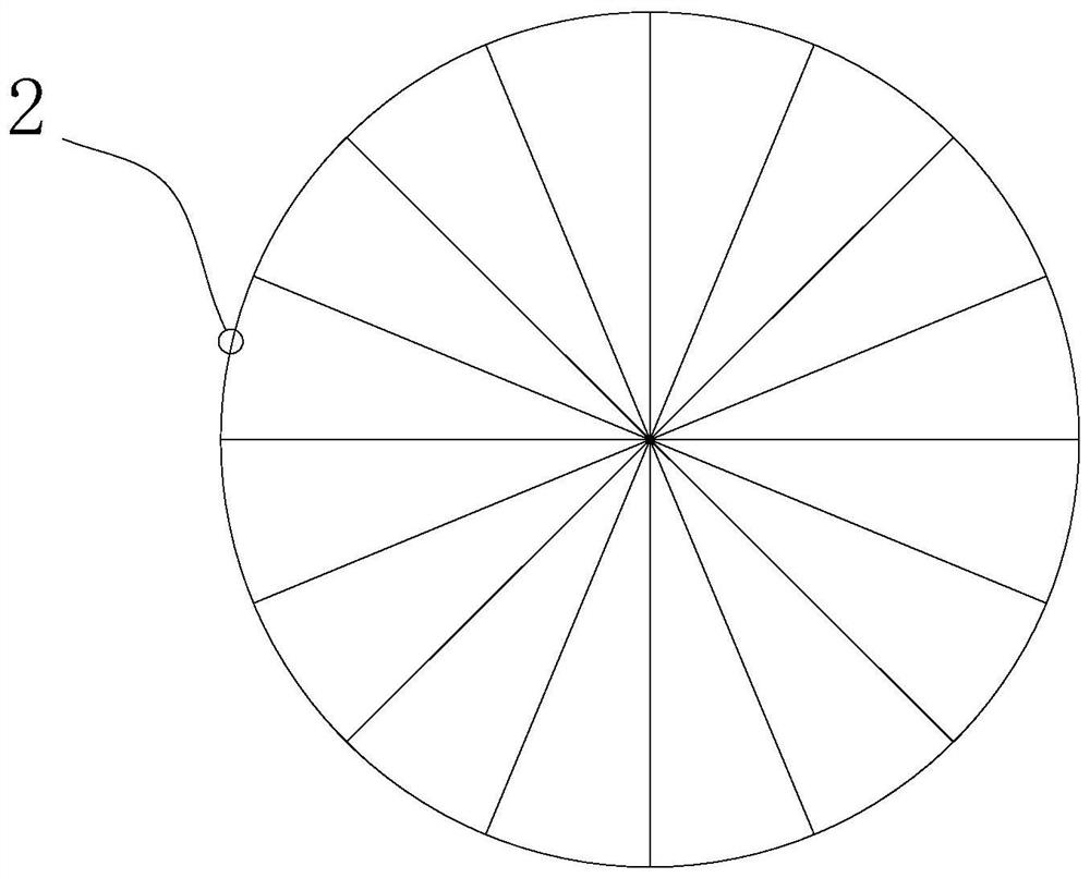
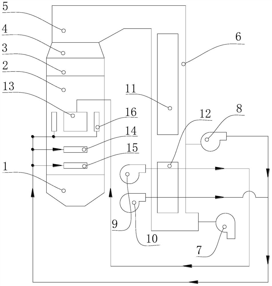
[0044] like figure 1 As shown, the supercritical carbon dioxide boiler system described in Example 1 includes an ash hopper 1, a main combustion chamber 2, an upper furnace 3, a flame angle 4, a horizontal flue 5, a tail flue 6, an induced draft fan 7, and a recirculation fan 8 , a primary blower 9 and a secondary blower 10, the ash hopper 1, the main combustion chamber 2, the upper furnace 3 and the refraction angle 4 are connected sequentially from bottom to top, and one end of the horizontal flue 5 is connected to the upper end of the refraction angle 4 Connected, one end of the tail flue 6 communicates with the other end of the horizontal flue 5, the air inlet of the induced draft fan 7 communicates with the other end of the tail flue 6, and is used for The flue gas is extracted from the inside to the outside, and the tail flue 6 is provided with a tail heating surface 11 and an air preheater 12 sequentially from one end close to the horizontal flue 5 to the other end.

...

Embodiment 2

[0050] like Figure 4 As shown, the supercritical carbon dioxide boiler system described in Example 2 includes an ash hopper 1, a main combustion chamber 2, an upper furnace 3, a flame angle 4, a horizontal flue 5, a tail flue 6, an induced draft fan 7, and a recirculation fan 8 , a primary blower 9 and a secondary blower 10, the ash hopper 1, the main combustion chamber 2, the upper furnace 3 and the refraction angle 4 are connected sequentially from bottom to top, and one end of the horizontal flue 5 is connected to the upper end of the refraction angle 4 Connected, one end of the tail flue 6 communicates with the other end of the horizontal flue 5, the air inlet of the induced draft fan 7 communicates with the other end of the tail flue 6, and is used for The flue gas is extracted from the inside to the outside, and the tail flue 6 is provided with a tail heating surface 11 and an air preheater 12 sequentially from one end close to the horizontal flue 5 to the other end.

...

Embodiment 3

[0057] The supercritical carbon dioxide boiler system described in embodiment 3 comprises a main combustion chamber 2, an upper furnace 3, a flame angle 4, a flue, an induced draft fan 7, a recirculation fan 8, a primary fan 9 and a secondary fan 10, and the upper furnace The lower end of the furnace 3 communicates with the upper end of the main combustion chamber 2, and the upper end of the upper furnace 3 communicates with one end of the flue through a flame angle 4, and the flue is provided with a tail heating surface 11 and air preheating 12, the air inlet of the induced draft fan 7 communicates with the tail of the flue.

[0058] The refraction angle 4 in this embodiment is in the shape of a truncated cone, and the included angle between the side wall of the refraction angle 4 and the horizontal plane is 50°.

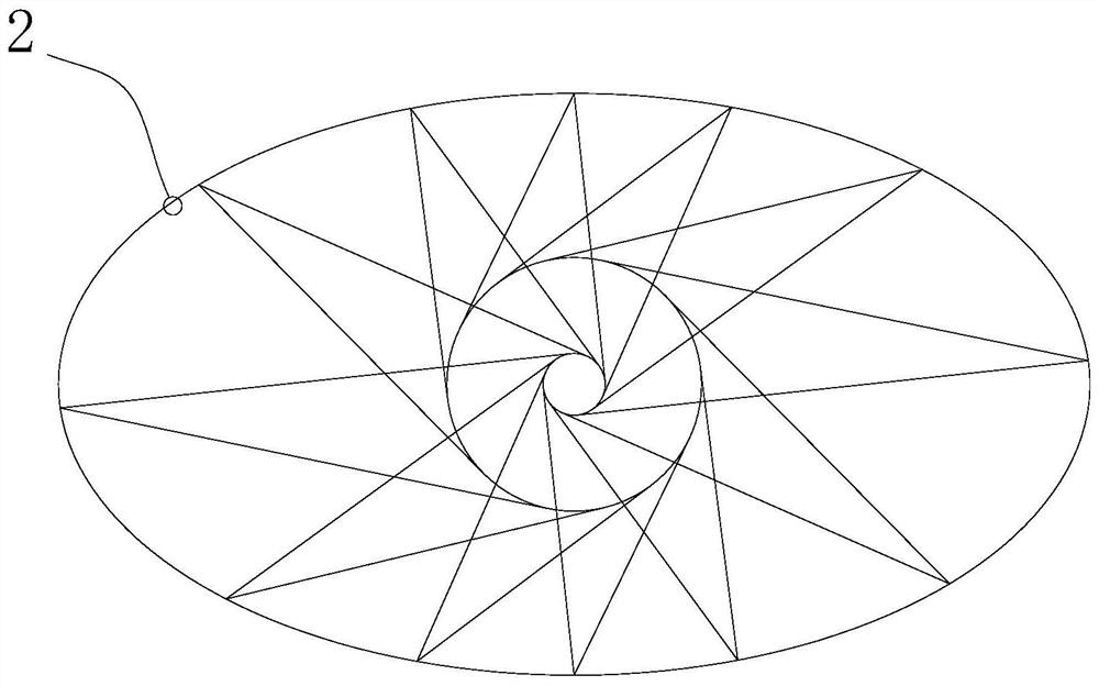
[0059] like Figure 5 As shown, the cross-section of the main combustion chamber 2 is a regular hexagon, and sixteen side walls of the main combustion chamber 2 a...


PUM


Abstract

The supercritical CO with uniform combustion and anti-corrosion and anti-coking disclosed in the present invention 2 The boiler and boiler system include the main combustion chamber, the upper furnace, the folding flame angle and the flue. The cross-section of the main combustion chamber is circular, oval or N-shaped, and N>4, and there are at least four Burner group, each group of burner nozzles corresponding to each burner group includes recirculation air nozzles, primary air nozzles and secondary air nozzles, and there are symmetrically distributed side recirculation air nozzles on both sides of the primary air nozzles. The nozzles and side recirculation air nozzles are used to feed recirculated flue gas or a mixture of recirculated flue gas and secondary air into the main combustion chamber, and the primary air nozzles are used to feed primary air or primary air and secondary air into the main combustion chamber. The mixed gas of the circulating flue gas, the secondary air nozzle is used to send the secondary air or the mixed gas of the secondary air and the recirculating flue gas into the main combustion chamber, so that the supercritical carbon dioxide boiler and the boiler system are loaded evenly, and avoid the boiler wall High temperature corrosion and coking and slagging occur.

Description

technical field [0001] The invention relates to the technical field of supercritical carbon dioxide boilers, in particular to an anti-corrosion and anti-coking supercritical carbon dioxide boiler and a boiler system. Background technique [0002] Supercritical carbon dioxide coal-fired power generation technology is currently a research hotspot in the world. This technology has the advantages of high efficiency, low cost and environmental protection. However, because the supercritical carbon dioxide boiler replaces the hydraulic medium in the traditional boiler with carbon dioxide, the traditional boiler structure cannot be fully applied to the supercritical carbon dioxide boiler. At present, the traditional large-scale coal-fired boilers are all rectangular structures, and then form four-corner tangential combustion, double tangential combustion or hedging combustion, but this method will inevitably lead to uneven distribution of combustion in the entire combustion chamber,...

Claims


Application Information

Patent Timeline
Patent Type & Authority Patents(China)
IPC IPC(8): F22B3/02F22B3/08F23C5/32F23C7/00F23C9/06F23L1/00F23L5/02F23L9/00F23M9/00
CPCF22B3/02F22B3/08F23C5/32F23C7/00F23C9/003F23C9/006F23C9/06F23L1/00F23L5/02F23L9/00F23M9/00
Inventor 向军朱萌周敬陈磊苏胜徐俊李艾书胡松汪一江龙韩亨达
Owner HUAZHONG UNIV OF SCI & TECH
Why Eureka
Try Eureka