
Ultrahigh-field animal magnetic resonance radio frequency probe with high dielectric constant

A high dielectric constant, radio frequency probe technology, applied in the direction of magnetic resonance measurement, magnetic variable measurement, measuring device, etc., can solve the problems of uneven distribution of current density, reduction of equivalent resistance, and poor sensitivity, so as to avoid coil mode Effects of increasing and disordering, improving emission efficiency, and improving sensitivity

Active Publication Date: 2021-01-01
INNOVATION ACAD FOR PRECISION MEASUREMENT SCI & TECH CAS
View PDF10 Cites 3 Cited by
  • Summary
  • Abstract
  • Description
  • Claims
  • Application Information

AI Technical Summary

Problems solved by technology

Adjust the shielding position by moving the shielding substrate, and then tune the coil ([3]DardzinskiB J, Li S, Collins C M, et al.A birdcage coil tuned by RF shielding for application at 9.4T[J].journal of magnetic resonance,1998, 131(1):32-38.) can improve the SNR and B to a certain extent 1 Field uniformity, but limited effect
Add end caps at both ends of the bird cage coil ([4]LouX, Gedney S D, Avison M J.End cap design for bird cage coils in nuclear magnetic resonance imaging[J].IEEE Transactions on Magnetics,1999,35(3):1939 -1946.) can increase the B near both ends of the coil 1 Field uniformity and sensitivity, but less noticeable effect on center position
[0007] Under the ultra-high field, due to the skin effect, the current density is unevenly distributed on the copper skin with a certain width, and it is mainly concentrated on the edge of the copper skin, which affects the B 1 Field uniformity; at the same time, the uneven current density distribution reduces the equivalent resistance, thereby reducing the B 1 field strength, leading to poor sensitivity

Method used


Image

  • Ultrahigh-field animal magnetic resonance radio frequency probe with high dielectric constant
  • Ultrahigh-field animal magnetic resonance radio frequency probe with high dielectric constant
  • Ultrahigh-field animal magnetic resonance radio frequency probe with high dielectric constant

Examples


Embodiment 1

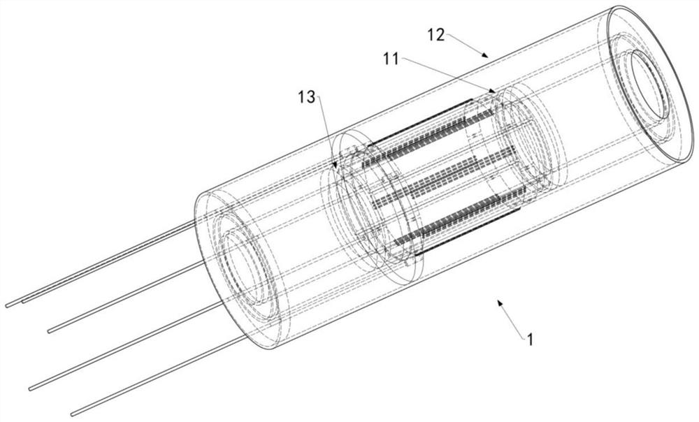
[0037] A magnetic resonance radio frequency probe 1 suitable for 7T mouse torso MRI, comprising a coil unit 12, a high dielectric constant ceramic unit 11 and a ceramic unit bracket 13, figure 1 It is a structural schematic diagram of the magnetic resonance radio frequency probe 1 . The high dielectric constant ceramic unit 11 is embedded between the coil circuit substrate 1210 and the inner wall substrate 1212 of the coil unit 12, and the two ends are fixed between the coil circuit substrate 1210 and the inner wall substrate 1212 by the ceramic unit bracket 13, forming a magnetic resonance radio frequency probe 1 .

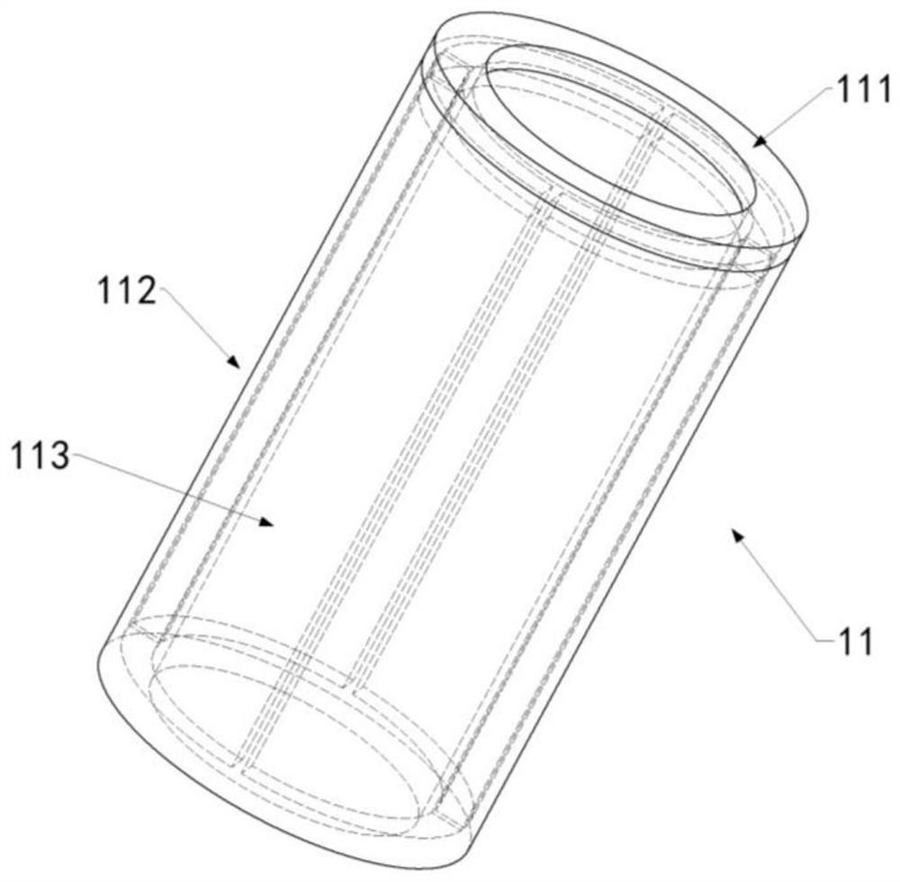
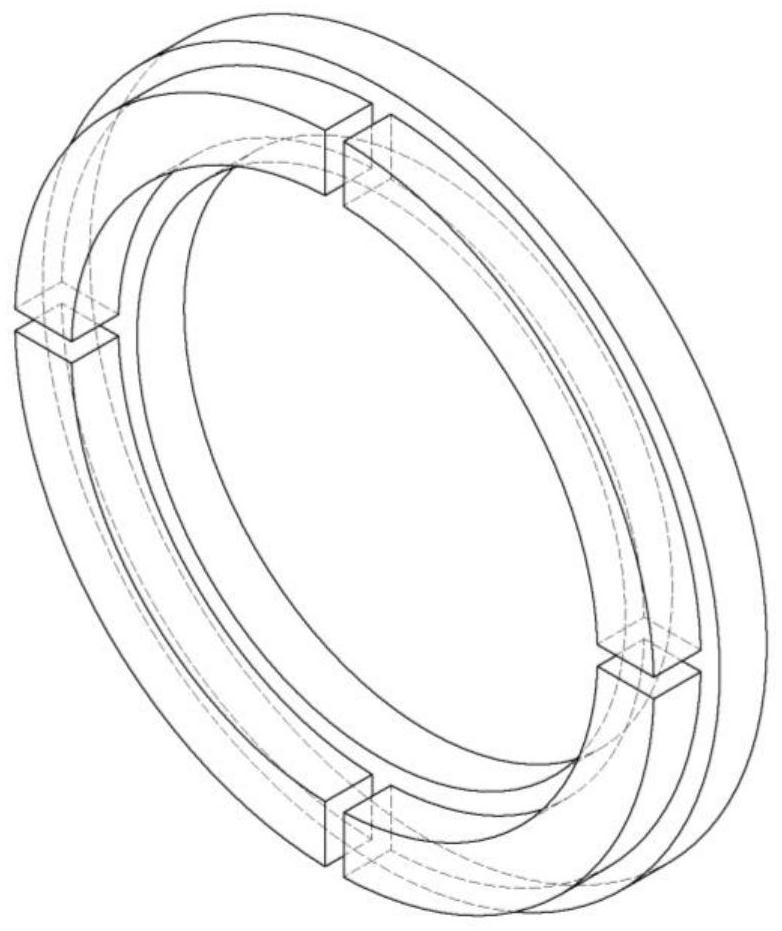
[0038] In this embodiment, the high dielectric constant ceramic unit 11 is made up of four high dielectric constant ceramic blocks 113 and a shell, figure 2 It is a structural schematic diagram of the high dielectric constant ceramic unit 11, Figure 4 (a) and (b) are an axial sectional view and a radial sectional view of the high dielectric constant ceramic u...


PUM


Abstract

The invention relates to a high-dielectric-constant ultrahigh-field animal magnetic resonance radio frequency probe which comprises a coil unit, the coil unit comprises a cylindrical coil circuit substrate and a cylindrical inner wall substrate, and the inner wall substrate is arranged in the coil circuit substrate. The two ends of a high-dielectric-constant ceramic unit are fixed between the coilcircuit substrate and the coil inner wall substrate through a ceramic unit support. All the units are independent of one another, assembling is flexible, and the sensitivity of the radio frequency probe can be effectively improved. The plurality of high-dielectric-constant ceramic blocks can greatly improve the B1 field emission efficiency in the central region, and avoids the adverse effects ofcoil mode increase and disorder caused by complete cylindrical barium titanate ceramic.

Description

technical field [0001] The invention relates to the technical field of magnetic resonance imaging, in particular to a high dielectric constant ultra-high field animal magnetic resonance radio frequency probe. Background technique [0002] The radio frequency coil is at the front end of the magnetic resonance imaging (Magnetic Resonance Imaging, MRI) system, and has a decisive influence on the sensitivity of the MRI signal. MRI, B 1 Field (weak magnetic field caused by radio frequency pulse) uniformity and sensitivity are two extremely important indicators to measure the performance of radio frequency coils. The birdcage coil has good symmetry such that B 1 The field distribution is fairly uniform. Due to its sensitivity and B 1 The advantage of field uniformity has been widely used in various animal MRI experiments, and has become a very classic MR radio frequency body coil. [0003] In conventional research, improving the signal-to-noise ratio of birdcage coils with B ...

Claims


Application Information

Patent Timeline
IPC IPC(8): G01R33/34G01R33/422
CPCG01R33/34076G01R33/422
Inventor 周欣唐德港石磊韩叶清孙献平
Owner INNOVATION ACAD FOR PRECISION MEASUREMENT SCI & TECH CAS
Learn More