Solar blind ultraviolet optical system with large relative aperture and large field of view

An optical system and relative aperture technology, applied in the field of solar-blind ultraviolet optical systems, can solve the problems of difficulty in having large relative aperture, high transmittance and high image surface uniformity.

Active Publication Date: 2021-01-01
FUJIAN FORECAM OPTICS CO LTD
View PDF7 Cites 0 Cited by
  • Summary
  • Abstract
  • Description
  • Claims
  • Application Information

AI Technical Summary

Problems solved by technology

In view of the fact that there are few commonly used optical materials in the ultraviolet band, mainly fused silica, calcium fluoride and magnesium fluoride, the chromatic aberration of the system has a great impact o

Method used


Image

  • Solar blind ultraviolet optical system with large relative aperture and large field of view
  • Solar blind ultraviolet optical system with large relative aperture and large field of view
  • Solar blind ultraviolet optical system with large relative aperture and large field of view

Examples


Embodiment Construction

[0024] In order to make the above-mentioned features and advantages of the present invention easier to understand, the following specific embodiments are described in detail with reference to the accompanying drawings, but the present invention is not limited thereto.

[0025] refer to Figure 1 to Figure 3

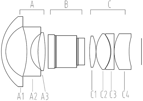
[0026] A sun-blind ultraviolet optical system with large relative aperture and large field of view, comprising a first lens A1, a second lens A2, a third lens A3, and a filter group B arranged at intervals along the optical axis from the object side to the image side , the fourth lens C1, the fifth lens C2, the sixth lens C3 and the seventh lens C4; the first lens is a meniscus negative lens, the second lens is a biconcave negative lens, and the third lens is a biconvex positive lens; The fourth lens is a biconvex positive lens, the fifth lens is a biconvex positive lens, the sixth lens is a plano-concave negative lens, and the seventh lens is a meniscus positive lens. ...


PUM


Abstract

The invention relates to a solar blind ultraviolet optical system with a large relative aperture and a large field of view, and is suitable for the technical field of optical instruments. The system comprises a first lens, a second lens, a third lens, an optical filter group, a fourth lens, a fifth lens, a sixth lens and a seventh lens which are sequentially arranged at intervals along an opticalaxis from an object side to an image side; the first lens is a meniscus negative lens, the second lens is a biconcave negative lens, and the third lens is a biconvex positive lens; and the fourth lensis a biconvex positive lens, the fifth lens is a biconvex positive lens, the sixth lens is a plano-concave negative lens, and the seventh lens is a meniscus positive lens. The optical system is suitable for an energy detection system in a solar blind ultraviolet spectrum region.

Description

technical field [0001] The invention relates to a sun-blind ultraviolet optical system with large relative aperture and large field of view, which is suitable for the technical field of optical instruments. Background technique [0002] Most of the high-voltage power equipment of transmission lines and substations work in the atmospheric environment. As the insulation performance of the equipment itself decreases, or the surface pollution and humidity increase, the electrical equipment will produce corona discharge. Corona discharge will not only cause power loss of the line, but also cause chemical reactions in the air to produce products such as ozone and nitrogen oxides, causing insulation corrosion and damage to transmission lines and electrical equipment. Therefore, timely and accurate detection of the location and strength of corona discharge is of great significance to ensure the reliable operation of the power system and reduce personal accidents and equipment damag...

Claims


Application Information

Patent Timeline
IPC IPC(8): G02B13/00G02B13/06G02B13/14G02B13/18G01J3/02G01J1/02
CPCG02B13/0045G02B13/06G02B13/18G02B13/143G01J3/0205G01J1/02
Inventor 康哲恺肖维军王芬尹邦雄
Owner FUJIAN FORECAM OPTICS CO LTD
Why Eureka
Try Eureka