Method for simulating silicon dioxide coated calcium fluoride based on Materials Studio

A calcium fluoride-coated, simulation method technology, applied in the field of computer simulation, can solve problems such as lack of research at the molecular level, and achieve the effect of reducing research and development costs and saving experimental resources

Active Publication Date: 2021-01-01
QILU UNIV OF TECH
View PDF6 Cites 2 Cited by
  • Summary
  • Abstract
  • Description
  • Claims
  • Application Information

AI Technical Summary

Problems solved by technology

[0005] However, the research on the mechanism of nanocomposite ceramic materials in the prior art still has

Method used


Image

  • Method for simulating silicon dioxide coated calcium fluoride based on Materials Studio
  • Method for simulating silicon dioxide coated calcium fluoride based on Materials Studio
  • Method for simulating silicon dioxide coated calcium fluoride based on Materials Studio

Examples


Embodiment 1

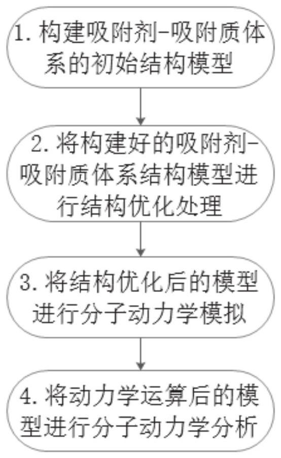
[0041]As attachedfigure 1 As shown, a simulation method of silica-coated calcium fluoride based on Materials Studio. In this embodiment, silica and calcium fluoride are used as the research object, which specifically includes the following steps:

[0042](1) Build initial models of silica and calcium fluoride;

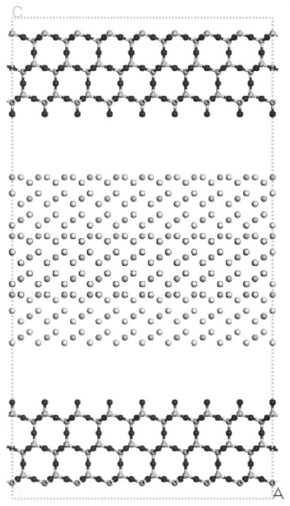
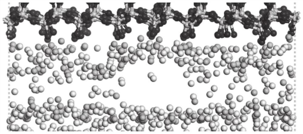
[0043]Use the Visualizer interface in the Materials Studio software to build the molecular structure model of silica and calcium fluoride, and cut the constructed model. Among them, layer 1 and layer 3 of the model are silica, and two types can be obtained after cutting. Terminal surface: O terminal and Si-O. The surface of O terminal is used as layer 1 and layer 3 of Model 1, and the surface of Si-O terminal is used as layer 1 and layer 3 of Model 2. The upper surface atoms of layer 2 are F and Ca For the mixed surface, the number of F and Ca is 100, and the number of atoms on the bottom surface is F, and the number is 100; use the Build layer tool in Build to establish a layered...

Embodiment 2

[0060]As attachedfigure 1 As shown, a simulation method of silica-coated calcium fluoride based on Materials Studio. In this embodiment, silica and calcium fluoride are used as the research object, which specifically includes the following steps:

[0061](1) Build initial models of silica and calcium fluoride;

[0062]Use the Visualizer interface in the Materials Studio software to build the molecular structure model of silica and calcium fluoride, and cut the constructed model. Among them, layer 1 and layer 3 of the model are silica, and two types can be obtained after cutting. Terminal surface: O terminal and Si-O, the O terminal surface is used as Model 3 layer 1 and layer 3, and the Si-O terminal surface is Model 4 layer 1 and layer 3, and the upper surface atom of layer 2 is F, and The number is 200, the lower surface atom is Ca, and the number is 100; use the Build layer tool in Build to establish a layered connection, and set a vacuum layer between the interfaces to obtain the sili...

Embodiment 3

[0078]As attachedfigure 1 As shown, a simulation method of silica-coated calcium fluoride based on Materials Studio. In this embodiment, silica and calcium fluoride are used as the research object, which specifically includes the following steps:

[0079](1) Build initial models of silica and calcium fluoride;

[0080]Use the Visualizer interface in the Materials Studio software to build the molecular structure model of silica and calcium fluoride, and cut the crystal plane of the constructed model. Among them, layer 1 and layer 3 of the model are silica, and two types can be obtained after cutting. Terminal surface: O terminal and Si-O. The surface of O terminal is used as layer 1 and layer 3 of Model 1, and the surface of Si-O terminal is used as layer 1 and layer 3 of Model 2. The upper surface atoms of layer 2 are F and Ca For the mixed surface, the number of F and Ca are both 100, and the number of atoms in the lower layer is F, and the number is 100; use the Build layer tool in Buil...


PUM


Abstract

The invention particularly relates to a method for simulating silicon dioxide coated calcium fluoride by using Matrials Studio software, which comprises the following steps: 1) constructing an initialmodel to be calculated by using software to obtain a silicon dioxide calcium fluoride molecular structure data file; 2) performing structure optimization on the initial model by utilizing a Force module in software; 3) performing molecular dynamics operation on the model by utilizing a Force module in software; 4) performing dynamic analysis on the model after dynamic processing; 5) calculating the interface distance and energy of the silicon dioxide calcium fluoride molecular structure to obtain distance and energy parameters; and 6) calculating to obtain the adsorption energy between the silicon dioxide and the calcium fluoride. Silicon dioxide coated calcium fluoride with complex procedures in the experiment process is simulated through the computer, detailed analysis is carried out from the atomic level, an experimenter is helped to analyze the simulated coating result, the experiment period is effectively shortened, the experiment cost is saved, a large number of experiments areavoided, and the safety of the experimenter is guaranteed.

Description

Technical field[0001]The invention relates to the technical field of computer simulation, in particular to a simulation method of silica-coated calcium fluoride based on Materials Studio.Background technique[0002]Disclosure of the background information is only intended to increase the understanding of the overall background of the present invention, and is not necessarily regarded as an acknowledgement or in any form suggesting that the information constitutes the prior art known to those of ordinary skill in the art.[0003]Compared with traditional ceramic materials, the strength and fracture toughness of nanocomposite ceramic materials have been greatly improved, and their wear resistance, hardness and high temperature performance have been greatly improved. Ceramic materials have a series of excellent special properties such as high temperature resistance, wear resistance, and corrosion resistance. However, the brittleness of ceramic materials limits its application.[0004]Calcium...

Claims


Application Information

Patent Timeline
IPC IPC(8): G16C10/00G16C20/10
CPCG16C10/00G16C20/10
Inventor 陈照强李琦许崇海肖光春衣明东张静婕
Owner QILU UNIV OF TECH
Why Eureka
Try Eureka