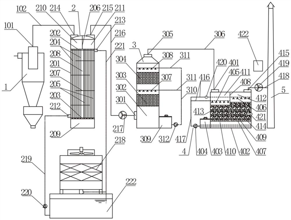
High-temperature waste gas deodorization treatment system

A high-temperature waste gas and treatment system technology, applied in the direction of air quality improvement, dispersed particle separation, chemical instruments and methods, etc., can solve the problem that the deodorization system cannot run continuously and stably, the effect of the deodorization system is not ideal, and the deodorization microorganisms are difficult to maintain activity And other issues

Pending Publication Date: 2021-01-05
广州中科建禹环保有限公司
View PDF0 Cites 2 Cited by
  • Summary
  • Abstract
  • Description
  • Claims
  • Application Information

AI Technical Summary

Problems solved by technology

Since the heat source of the steam indirect heat drying system is saturated steam, the sludge in the sludge heat dryer can be heated to about 90°C, so the temperature of the waste gas generated by heating the sludge is also about 90°C, which is difficult for general deodorizing microorganisms Such a high-temperature gas, and it is difficult to meet the temperature requirements of microorganisms after simple spraying, making it difficult for deodorizing microorganisms to maintain activity, and the overall deodorizing system is not ideal
If the biological deodorization device is not used, but the deodorization spray device is simply used, the change of the odor component in the exhaust gas is often caused by the change of the sludge sludge, and the simple deodorization spray device has no load to withstand the change of the odor component, resulting in The deodorization system cannot operate continuously and stably

Method used


Image

  • High-temperature waste gas deodorization treatment system

Examples


Embodiment Construction

[0025] In order to enable those skilled in the art to better understand the technical solution of the present invention, the present invention will be described in further detail below in conjunction with the accompanying drawings and specific embodiments. And the features in the embodiments can be combined with each other.

[0026] In describing the present invention, it is to be understood that the terms "center", "longitudinal", "transverse", "length", "width", "thickness", "upper surface", "lower surface", "front" , "Back", "Left", "Right", "Vertical", "Horizontal", "Top", "Bottom", "Inner", "Outer", "Forward", "Reverse", "Axial ", "radial", "circumferential" and other indicated orientations or positional relationships are based on the orientations or positional relationships shown in the drawings, which are only for the convenience of describing the present invention and simplifying the description, rather than indicating or implying the referred device Or elements must ...


PUM


Abstract

The invention discloses a high-temperature waste gas deodorization treatment system which is characterized by comprising a dust removal device, a condensation device, a deodorization spraying device,a biological deodorization device and a discharge chimney. Sludge drying high-temperature waste gas sequentially passes through the dust removal device, the condensation device, the deodorization spraying device and the biological deodorization device and then is discharged from the discharge chimney. High-temperature waste gas generated by a municipal sludge drying system enters the dust removaldevice under the action of an induced draft fan, and dust carried in the waste gas is removed in the dust removal device; the waste gas subjected to dust removal enters the condensation device, the temperature of the waste gas is reduced to 45-50 DEG C suitable for microorganisms under the action of circulating cooling water, and stable operation of subsequent biological deodorization is guaranteed; then the waste gas enters the deodorization spraying device, and hydrogen sulfide and odor in the waste gas are removed through chemical spraying; the sprayed waste gas enters the biological deodorization device, and hydrogen sulfide, ammonia and odor in the waste gas are further removed under the action of microorganisms; and finally, the up-to-standard waste gas is discharged through the chimney.

Description

technical field [0001] The invention relates to a waste gas deodorization system, in particular to a high-temperature waste gas treatment system produced in the field of municipal sludge drying. Background technique [0002] With the promotion of municipal sludge reduction, the existing sludge filter press system is difficult to meet the moisture content of sludge landfill and incineration (①co-incineration with garbage, ②co-incineration in cement kiln, ③coal blending in power plants) It needs to be controlled at the requirement of 30%~40%. More and more municipal sewage treatment plants add sludge thermal drying treatment system on the basis of the original sludge filter press system. [0003] At present, the more mature technical methods for thermal drying of sewage plant sludge in China include electric energy heat pump drying and steam indirect thermal drying. Because steam indirect heat drying has the advantages of wide applicability, low energy consumption, high effi...

Claims


Application Information

Patent Timeline
Patent Type & Authority Applications(China)
IPC IPC(8): B01D53/84B01D53/52B01D45/12
CPCB01D53/84B01D53/52B01D45/12Y02A50/20
Inventor 徐坤陈美洁周秀霞何程勇
Owner 广州中科建禹环保有限公司
Why Eureka
Try Eureka