Novel piezoelectric ceramic valve driving control system

A technology of piezoelectric ceramics and control systems, which is applied in coatings and devices for coating liquids on the surface, etc. It can solve the problems that the needle movement stroke cannot be adjusted accurately, the dispensing valve cannot continue to work stably, and the cost of high-voltage operational amplifiers is expensive, etc. problems, to achieve the effect of improving stability and security, enhancing market competitiveness, and avoiding errors

Active Publication Date: 2021-01-05
深圳市轴心压电技术有限公司
View PDF11 Cites 4 Cited by
  • Summary
  • Abstract
  • Description
  • Claims
  • Application Information

AI Technical Summary

Problems solved by technology

[0003] At present, in the application of two-component valves, in order to improve the accuracy of the glue output control, the control scheme of the piezoelectric ceramic driver usually adopts a linear high-voltage operational amplifier and a linear amplifier circuit composed of a post-stage power amplifier circuit. This drive circuit Suitable for static positioning or low-speed reciprocating vibration of piezoelectric ceramics. Due to the integrated structure of the spray needle and the amplifying transmission mechanism, the guide of the spray needle is poor, easy to interfere, easy to loosen, the movement stroke of the spray needle cannot be adjusted accurately, and the glue chamber is sealed The performance is poor, the dispensing valve cannot continue to work stably, and the high-voltage operational amplifier is expensive, and the efficiency of the amplifier is low, the heat is serious, the output load capacity is limited, the high-speed dynamic response is slow, and it cannot meet the process requirements for further improving the accuracy of the glue output. , therefore, it is urgent to improve the drive controller of the existing piezoelectric injection valve body

Method used


Image

  • Novel piezoelectric ceramic valve driving control system
  • Novel piezoelectric ceramic valve driving control system
  • Novel piezoelectric ceramic valve driving control system

Examples


Embodiment Construction

[0027] In order to make the purpose, technical solutions and advantages of the embodiments of the present disclosure clearer, the technical solutions in the embodiments of the present disclosure will be clearly and completely described below in conjunction with the drawings in the embodiments of the present disclosure. Apparently, the described embodiments are some of the embodiments of the present disclosure, not all of them. Based on the embodiments in the present disclosure, all other embodiments obtained by persons of ordinary skill in the art without creative efforts fall within the protection scope of the present disclosure.

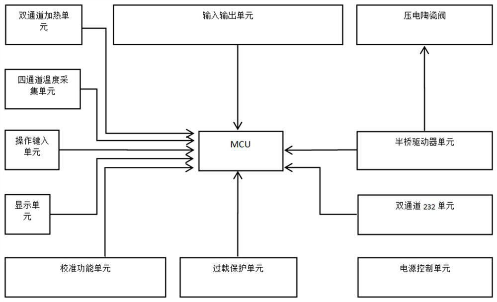
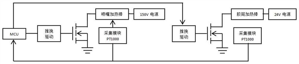
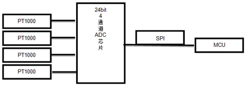
[0028] Such as figure 1 , Figure 4 As shown, a novel piezoelectric ceramic valve drive control system described in the present invention includes a controller and a piezoelectric ceramic valve. The controller includes an MCU, a dual-channel heating unit, a four-channel temperature acquisition unit, and an input and output unit. , operation input...


PUM


Abstract

The invention belongs to the technical field of dispensing valve control, and particularly relates to a novel piezoelectric ceramic valve driving control system. The novel piezoelectric ceramic valvedriving control system comprises a controller and a piezoelectric ceramic valve. The controller is internally provided with an MCU, a dual-channel heating unit, a four-channel temperature acquisitionunit, an input and output unit, an operation typing unit, a display unit and a power supply control unit. A single-line EEPROM chip is arranged in the piezoelectric ceramic valve and connected to theMCU to be used for recording glue spraying information of the piezoelectric ceramic valve. A half-bridge driver unit is further arranged between the piezoelectric ceramic valve and the controller. According to the novel piezoelectric ceramic valve driving control system, the energy conversion efficiency is higher, the dynamic response speed is faster, higher driving frequency can be supported, theheating value of the controller is very small, an expensive high-voltage operational amplifier is omitted, the cost of an electronic BOM is saved, the economical efficiency is very good, and the structural design of the controller can be more miniaturized and integrated.

Description

technical field [0001] The invention belongs to the technical field of dispensing valve control, in particular to a novel piezoelectric ceramic valve drive control system. Background technique [0002] With the development of industry and the advancement of science and technology, various industries are becoming more and more intelligent, and the service life and stability of products are also more and more valued by users. At present, dispensing technology is widely used in microelectronics packaging, life sciences, rapid manufacturing and other fields. In the process of microelectronic packaging, dispensing technology is mainly used for chip bonding, chip coating, underfill, LED packaging, etc. According to its working principle, dispensing technology can be divided into two categories: contact dispensing and non-contact dispensing. Non-contact dispensing has the advantages of good glue point consistency, high working frequency, small glue droplet volume and wide glue ra...

Claims


Application Information

Patent Timeline
IPC IPC(8): B05C5/02
CPCB05C5/0225
Inventor 余晨光张洋
Owner 深圳市轴心压电技术有限公司
Why Eureka
Try Eureka