Phase-locked loop circuit, setting method thereof and communication equipment

A phase-locked loop and circuit technology, which is applied in the field of communication, can solve the problems of increased phase deviation temperature change, large power consumption, and the inability to ensure that the phase difference is less than the set value, so as to meet the needs of phase synchronization, save energy consumption, The effect of improving resource utilization

Pending Publication Date: 2021-01-05
ZTE CORP
View PDF0 Cites 0 Cited by
  • Summary
  • Abstract
  • Description
  • Claims
  • Application Information

AI Technical Summary

Problems solved by technology

Due to the limitation of cost and board area, currently one channel corresponds to one PLL circuit. Since the PLL circuit has the characteristic of phase shift with temperature changes, the phase deviation between multiple channels varies with the temperature. increase with temperature change
For this problem, in order to meet the requirement that the phase difference between multiple channels is less than the set value (for example, 5°), the current practice is that the wireless base station system adopts a series of phase detection and adjustment measures to reduce the phase error between channels. Then align the phases of multi-channel signals; for example, phase detection and alignment control are performed every 30 minutes. This phase detection alignment processing method needs to occupy a lot of system resources and generate large power consumption, and it cannot guarantee that the detection time interval The phase difference between multiple channels within the set value is less than the requirement
Therefore, how to fundamentally ensure multi-channel phase synchronization is a major technical bottleneck in base station applications

Method used


Image

  • Phase-locked loop circuit, setting method thereof and communication equipment
  • Phase-locked loop circuit, setting method thereof and communication equipment
  • Phase-locked loop circuit, setting method thereof and communication equipment

Examples


Embodiment 1

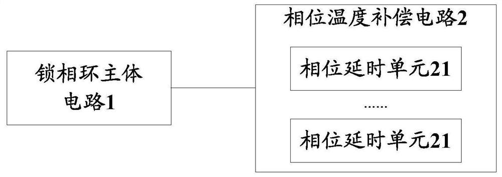
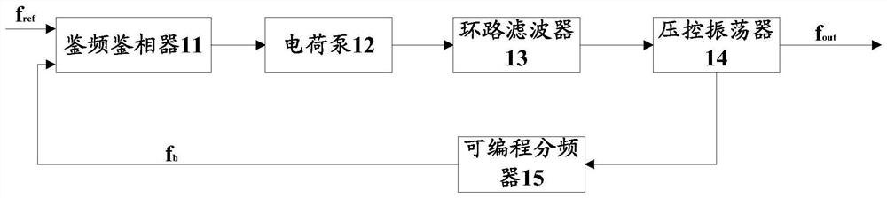
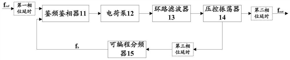
[0060] Aiming at the problem that the phase deviation between channels gradually increases as the temperature changes with multiple channels using multiple phase-locked loop circuits due to the phase-shift characteristic of the phase-locked loop circuit; The embodiment of the present invention provides a phase synchronous phase-locked loop circuit that can fundamentally realize multi-channel. See figure 1 As shown, the PLL circuit in this embodiment includes a PLL main circuit 1 and a phase temperature compensation circuit 2, wherein the phase temperature compensation circuit 2 includes at least one phase delay unit 21, and at least one phase delay unit 21 is connected to Into the PLL main circuit 1, the phase offset generated by the phase delay unit 21 connected to the PLL main circuit 1 as the temperature changes, and the phase offset produced by the PLL main circuit 1 as the temperature changes cancel each other . In order to ensure that the phase-locked loop circuit does...

Embodiment 2

[0085] In order to facilitate understanding, this embodiment will illustrate the setting method of the phase-locked loop circuit shown in the first embodiment on the basis of the first embodiment above, please refer to Figure 5 shown, including:

[0086] S501: Obtain the phase offset generated by the phase-locked loop main circuit 1 as the temperature changes through simulation.

[0087] For example, in one example, the phase and temperature change slopes K1, K2, and K3 of the reference signal input path, feedback signal transmission path, and signal output path can be simulated based on the collected data, so as to obtain the transmission path of the phase-locked loop main circuit 1 Its total output phase and temperature change slope Kout=K1+K2-K3.

[0088] S502: Determine a phase delay unit control parameter according to the obtained phase offset.

[0089] For example, in an example, it can be determined according to Kout=K1+K2-K3 which paths need to be connected to the p...

Embodiment 3

[0115] For ease of understanding, this embodiment will be described below by taking several specific application scenarios as examples.

[0116] Application scenario one:

[0117] In this application scenario, see Figure 13-2 to Figure 13-4 As shown, the relationship between the phase and temperature slope of the reference signal input path, signal output path, and feedback signal transmission path is K1+K2-K3>0. If the phase delay unit is not connected, the final output phase of the phase-locked loop circuit will vary with the temperature rise and increase. In this embodiment, a corresponding number of phase delay units are connected to the feedback signal transmission path to generate the corresponding Kc3, please refer to Figure 13-1 and Figure 13-5 As shown, the reference signal input path and the signal output path are not currently connected to the phase delay unit; the output phase of the connected phase delay unit increases with temperature, due to the phase dela...


PUM


Abstract

An embodiment of the invention provides a phase-locked loop circuit, a setting method of the phase-locked loop circuit and communication equipment. The phase-locked loop circuit comprises a phase-locked loop main body circuit and a phase temperature compensation circuit, wherein the phase-locked loop circuit is capable of configuring, according to a phase shift generated by the phase-locked main body circuit as a result of a temperature change, at least one phase delay unit of the phase temperature compensation circuit to be connected to the phase-locked loop main body circuit, and cancellingout the phase shift generated by the phase-locked loop main body circuit along with the temperature change by utilizing the phase shift generated by the phase delay unit which is connected to the phase temperature compensation circuit along with the temperature change. Therefore, the phase-locked loop circuit is ensured not to generate phase shift or generate phase shift in a very small range along with the temperature change in the working process. When the phase-locked loop circuit is applied to multi-channel communication, as the phase-locked loop circuit of each channel does not generate phase shift along with the temperature change or generates phase shift within a very small range, the phase difference between the channels can be as small as possible at any moment, and the synchronization requirement is fundamentally met.

Description

technical field [0001] The invention relates to the technical field of communication, in particular to a phase-locked loop circuit, a setting method thereof, and a communication device. Background technique [0002] And with the development of communication technology, multi-array antenna base stations and multi-transceiver channel complete machines are 4G and 5G (5G th -Generation, a typical application in the 5th generation) communication technology; in 5G communication, Space Division Multiple Access (SDMA) is an important example of the application of Maximum Input Minimum Output (MassiveMIMO) technology. SDMA uses beamforming technology to concentrate signal energy in a specific direction, thereby increasing spectrum utilization efficiency and reducing interference to other receivers. Beamforming has strict requirements on the phase difference of signals between multiple channels of transceivers. For example, the phase difference between multiple channels of sub 6G 5G ...

Claims


Application Information

Patent Timeline
Patent Type & Authority Applications(China)
IPC IPC(8): H03L1/02H03L1/04H03L7/10H03L7/08
CPCH03L1/022H03L1/04H03L7/10H03L7/0802H03L1/02H03L7/081Y02D30/70
Inventor 刘俊韦兆碧王珊段沛雷梦毕
Owner ZTE CORP
Why Eureka
Try Eureka