Drying device for textile printing and dyeing

A drying device and textile printing and dyeing technology, which is applied in the field of textile processing, can solve the problems of low degree of completeness and low drying rate of cloth drying, and achieve the effect of expanding the cleaning and drying range and promoting drying

Inactive Publication Date: 2021-01-08
汪钱洪
View PDF1 Cites 4 Cited by
  • Summary
  • Abstract
  • Description
  • Claims
  • Application Information

AI Technical Summary

Problems solved by technology

The drying device for textile printing and dyeing is inserted into the feeding nip roller through one end of the textile fabric body, and the textile fabric body is driven by the feeding nip roller to cooperate with the auxiliary nip roller to limit the position of the textile fabric body, and the hot air blower on the top of the mounting seat passes through The hot air pipe heats the inside of the drying box to dry the textile fabric body; although this device can be used to dry textile fabrics, the drying of the fabrics is not sufficiently comprehensive and the drying rate is low For this reason, a drying device for textile printing and dyeing is now provided to solve the above technical problems

Method used


Image

  • Drying device for textile printing and dyeing
  • Drying device for textile printing and dyeing
  • Drying device for textile printing and dyeing

Examples


Embodiment 1

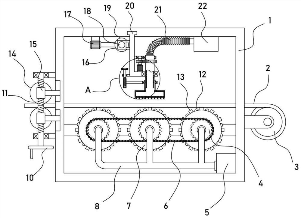
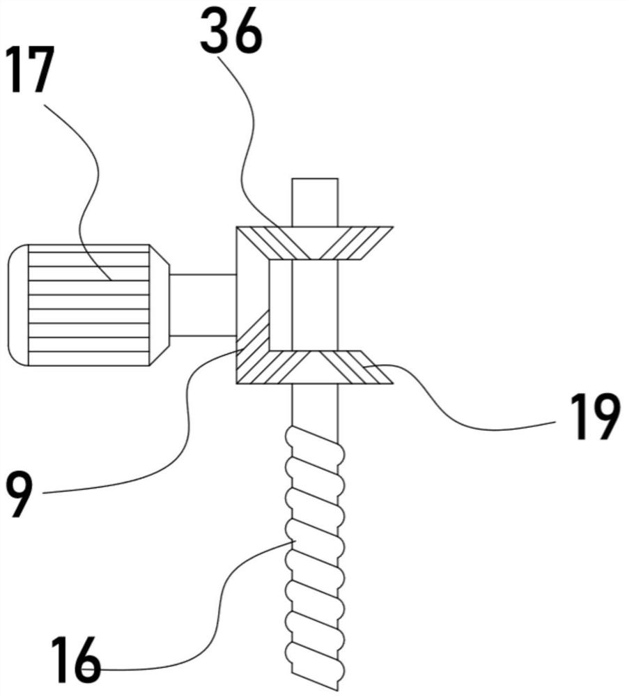
[0022] see Figure 1-4 , a drying device for textile printing and dyeing, including a fixed frame 1, a winding roller 3 is installed on the fixed frame 1, and a cloth 2 is wound on the winding roller 3, and a hot air blower is fixed on the fixed frame 1 5. The hot air blower 5 is connected with a drying mechanism for the user to dry the cloth 2, and the fixed frame 1 is installed with a hand handle 10 for rotation, and the hand handle 10 is driven and connected with a device for rolling the cloth 2. Leveling mechanism, the fixed frame 1 is provided with a translation frame 25, the fixed frame 1 is fixed with a vacuum cleaner 22, the vacuum cleaner 22 is connected and installed with a dust suction mechanism for removing dust from the cloth 2, and the fixed frame 1 is fixed with a drive motor 17. The driving motor 17 is connected with a longitudinal translation mechanism for driving the translation frame 25 to translate longitudinally.

[0023] In this device, the cloth 2 is wo...

Embodiment 2

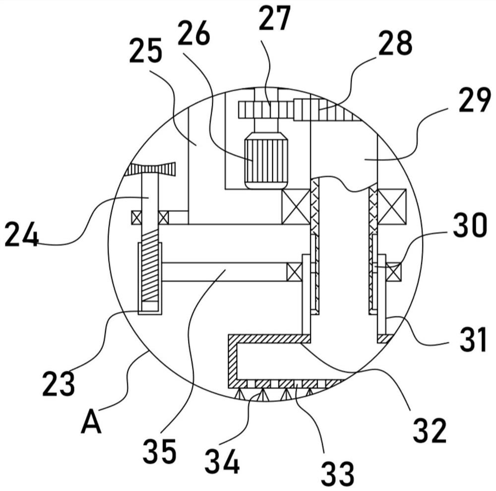
[0029] On the basis of Embodiment 1, in addition, the dust suction mechanism of the device includes a rotating tube 29 that is rotatably installed on the translation frame 25. The sealing sleeve on the rotating tube 29 is provided with a sleeve 31, and the bottom of the sleeve 31 is communicated with and installed with A suction pan 32, the bottom of the suction pan 32 is evenly provided with several air inlets 33, a brush 34 is installed on the bottom of the suction pan 32, a bellows 21 is installed at the inlet end of the vacuum cleaner 22, and the end of the bellows 21 is rotated The joint is connected with the rotating tube 29, and the driven gear 28 is sheathed and fixed on the rotating tube 29, and the driving gear 27 driven by the driven gear 28 is meshed and connected with the driven gear 27.

[0030] The vacuum cleaner 22 can suck air through the bellows 21, and the fluff or thread ends on the surface of the cloth 2 enter the dust suction plate 32 from the air inlet 33...


PUM


Abstract

The invention discloses a drying device for textile printing and dyeing, and relates to the technical field of textile processing. The drying device comprises a fixing frame; a dust collector is fixedon the fixing frame; the dust collector communicates with a dust collection mechanism for dedusting cloth; a driving motor is in transmission connection with a longitudinal translation mechanism fordriving a translation frame to longitudinally translate. Printed and dyed cloth can be rolled and flattened through a flattening mechanism, subsequent stable conveying and moving of the cloth are achieved, and a drying mechanism can convey hot air through a rotating spray head, and the hot air drying effect on the cloth is achieved. The arranged dust collection mechanism can absorb rising damp andhot air to promote rising flow of hot air flow to promote drying of cloth; and meanwhile, a brush can rotate along with a dust collection disc to achieve the cleaning effect on the surface of the cloth, the effect of absorbing fine fluff or thread residues is achieved, and the printing, dyeing, drying and forming quality of the cloth is effectively guaranteed.

Description

technical field [0001] The invention relates to the technical field of textile processing, in particular to a drying device for textile printing and dyeing. Background technique [0002] The original meaning of textile is taken from the general term of spinning and weaving, but with the continuous development and improvement of the textile knowledge system and subject system, especially after the emergence of non-woven textile materials and three-dimensional composite weaving technologies, it is not only the traditional hand spinning And weaving, also including non-woven fabric technology, modern three-dimensional weaving technology, modern electrostatic nano-netting technology and other clothing, industrial and decorative textiles. After printing and dyeing on the surface of the textile fabric, it is necessary to dry the fabric through a drying device. [0003] The patent with the authorized notification number CN210085780U discloses a drying device for textile printing an...

Claims


Application Information

Patent Timeline
Patent Type & Authority Applications(China)
IPC IPC(8): D06B15/09D06B23/04D06G1/00
CPCD06B15/09D06B23/04D06G1/00
Inventor 汪钱洪
Owner 汪钱洪
Why Eureka
Try Eureka