Rapid printing device for textiles

A textile and fast technology, applied in printing devices, printing, printing machines, etc., can solve the problems of inconvenient printing and dyeing, low pass rate of printing and dyeing, etc., and achieve the effects of improving work efficiency, avoiding damage, improving work efficiency and pass rate

Pending Publication Date: 2021-12-31
YANCHENG INST OF TECH
View PDF8 Cites 0 Cited by
  • Summary
  • Abstract
  • Description
  • Claims
  • Application Information

AI Technical Summary

Problems solved by technology

[0004] The purpose of the present invention is to provide a rapid printing device for textiles, which solves the problems of inconvenient printing and dyeing of small patterns on the surface of textile fabrics and low printing and dyeing pass rate in the prior art

Method used


Image

  • Rapid printing device for textiles
  • Rapid printing device for textiles
  • Rapid printing device for textiles

Examples


Embodiment 1

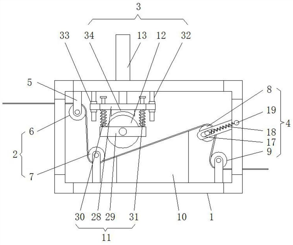
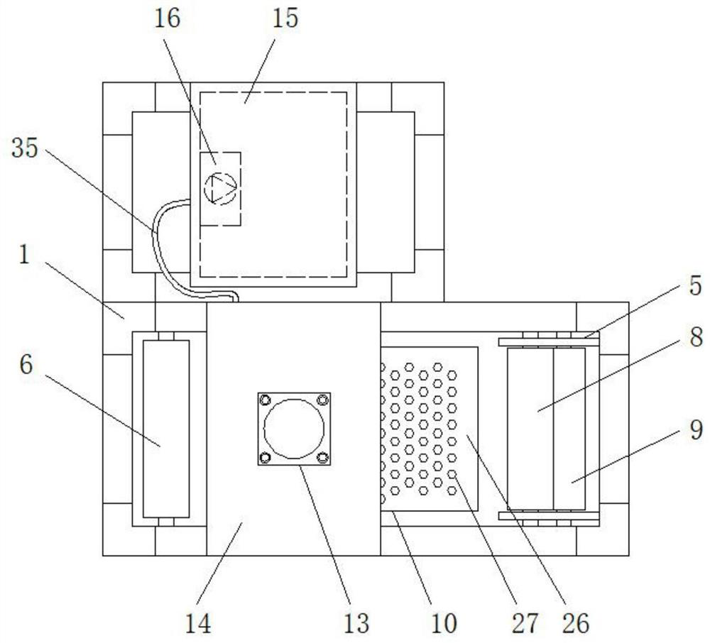
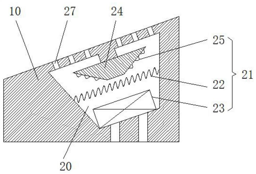
[0033] When the present invention is working, the textile cloth is fed into the printing and dyeing mechanism 3 along the feed roller group 2 and discharged from the discharge roller group 4, and the hydraulic rod 13 pushes the printing and dyeing frame 11 to move downward, so that the printing and dyeing roller 12 is closely attached to the surface of the textile cloth , as the movement of the textile cloth drives the printing and dyeing roller 12 to rotate, the printing and dyeing roller 12 transfers the pattern on its surface to the surface of the textile cloth, and the printed textile cloth continues to move along the surface of the printing and dyeing table 10 to the air outlet 27, and the fan 23 will The heat generated by the thermal resistance wire 22 is blown to the surface of the textile fabric, which facilitates rapid drying of the dyes on the surface of the textile fabric, and improves the working efficiency and printing quality of the printing and dyeing process.

Embodiment 2

[0035] When the present invention is carrying out printing and dyeing processing, the pump body 16 in the dye tank 15 regularly sends the dye to the painting pad 34 under the control of the relay, so as to ensure the painting efficiency of the painting pad 34 on the printing and dyeing roller 12, and the painting pad 34 The dye inside is fully absorbed by the sponge pad 37, and the dye is evenly coated on the surface of the printing and dyeing roller 12 when the printing and dyeing roller 12 rotates, thereby ensuring that the printing and dyeing roller 12 quickly prints and dyes the textile cloth.


PUM


Abstract

The invention discloses a rapid printing device for textiles. The rapid printing device comprises a rack, a feeding roller set, a printing and dyeing mechanism and a discharging roller set, the feeding roller set, the printing and dyeing mechanism and the discharging roller set are sequentially arranged in the rack from left to right, a U-shaped frame is arranged among the feeding roller set, the discharging roller set and the rack, the feeding roller set is composed of a first guide roller and a steering roller, the discharging roller set is composed of a tensioning roller and a second guide roller, the printing and dyeing mechanism comprises a printing and dyeing table, a printing and dyeing frame, a printing and dyeing roller and a hydraulic rod, the printing and dyeing table is fixedly connected with the bottom of the rack, the printing and dyeing frame is arranged above the printing and dyeing table, and the printing and dyeing roller in rotational connection is arranged at the bottom of the printing and dyeing frame. The printing and dyeing frame with the printing and dyeing roller is arranged above the printing and dyeing table, the printing and dyeing roller can be conveniently pushed by the hydraulic rod to be tightly attached to the surface of the printing and dyeing table, a drying assembly is fixedly connected in the printing and dyeing table, dye is prevented from being diffused on the surface of textile fabric, and the working efficiency and the qualified rate of textile fabric printing and dyeing are improved.

Description

technical field [0001] The invention relates to the technical field of textile processing, in particular to a rapid printing device for textiles. Background technique [0002] China is a big country in the production and export of textiles. After years of development, China's textile industry has obvious competitive advantages. It has the most complete industrial chain in the world, the highest level of processing facilities, and many developed industrial clusters to respond to market risks. Self-regulation The continuous enhancement of capabilities provides a solid guarantee for the industry to maintain a steady pace of development. From the perspective of the international environment, there is still a lot of room and opportunity for expansion in the international market. With the expiry of the China-Europe textile quotas at the end of 2007 and the end of the Sino-US textile quotas at the end of 2008, the era of China's textile quota-free is approaching, and the regions a...

Claims


Application Information

Patent Timeline
Patent Type & Authority Applications(China)
IPC IPC(8): B41F17/00B41F23/04B41F13/02
CPCB41F17/003B41F23/0426B41F13/02B41P2217/50
Inventor 林玲王春霞贾高鹏季葛希杨浙
Owner YANCHENG INST OF TECH
Why Eureka
Try Eureka