
Power supply filter with high-efficiency electromagnetic isolation and heat dissipation functions

A power filter and electromagnetic isolation technology, which is applied to the circuit layout on the support structure, electrical components, magnetic field/electric field shielding, etc., can solve the problem of easy loosening and damage of inductors, non-targeted setting of insulating substrates, and breakdown of filter circuits Damage and other problems, to avoid voltage breakdown short circuit problem, good electromagnetic shielding effect, high stability welding connection effect

Pending Publication Date: 2021-01-08
CHENGDU HONGMING ELECTRONICS CO LTD
View PDF0 Cites 0 Cited by
  • Summary
  • Abstract
  • Description
  • Claims
  • Application Information

AI Technical Summary

Problems solved by technology

[0004] The inner cavity of the shell of the traditional power filter is generally an integral inner cavity. In order to meet various test requirements, after installing various electronic components, they will be potted and fixed with potting glue, so there are the following defects: Poor shielding effect and poor electromagnetic compatibility; independent maintenance of some electronic components cannot be realized. Once a component is damaged, it generally needs to be replaced as a whole, which increases the cost of use
[0005] The heat dissipation method of the traditional power filter is generally a direct contact heat transfer process, that is, the heat generated by the heating element is transferred to the shell through the direct contact or through the potting glue to achieve heat dissipation. There are the following defects: the heat dissipation effect is insufficient, and the internal temperature of the shell The rise is fast, and it will damage electronic components and filters in severe cases
[0006] The lead wire connection of the traditional power filter adopts the conventional screw or small hole welding method, which has the following problems: there is no targeted setting of the insulating substrate, and the insulation function is generally realized by setting a certain distance, and the lead wire connection function is realized through the connecting column, etc., neither Sufficient insulation performance and safety performance, but it is not convenient to realize good lead wire connection function; at the same time, for the lead wire connection of large current and high voltage, the welding is not stable enough, and the traditional power filter has a large connection resistance, which generates a large partial voltage and causes voltage The problem of serious loss, and there may be problems such as solder melting and diffusion at the connection, resulting in circuit failure and other problems
[0007] The inductor of the traditional power filter is installed with a simple bracket, which has the following defects: it is difficult to achieve stable installation for the large volume and heavy inductor required for high current, and the inductor is easy to loosen and damage when it is in a vibrating environment
[0008] There is no circuit designed to prevent reverse connection in the filter circuit of the traditional power filter, and there are the following defects: if there is a wrong operation and the positive and negative poles of the power input are reversed, the filter circuit may be damaged by breakdown due to reverse voltage

Method used


Image

  • Power supply filter with high-efficiency electromagnetic isolation and heat dissipation functions
  • Power supply filter with high-efficiency electromagnetic isolation and heat dissipation functions
  • Power supply filter with high-efficiency electromagnetic isolation and heat dissipation functions

Examples


Embodiment Construction

[0041] The present invention will be further described below in conjunction with accompanying drawing:

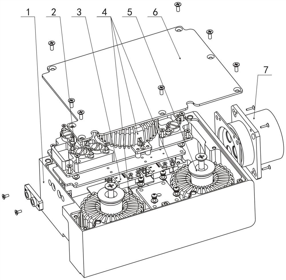
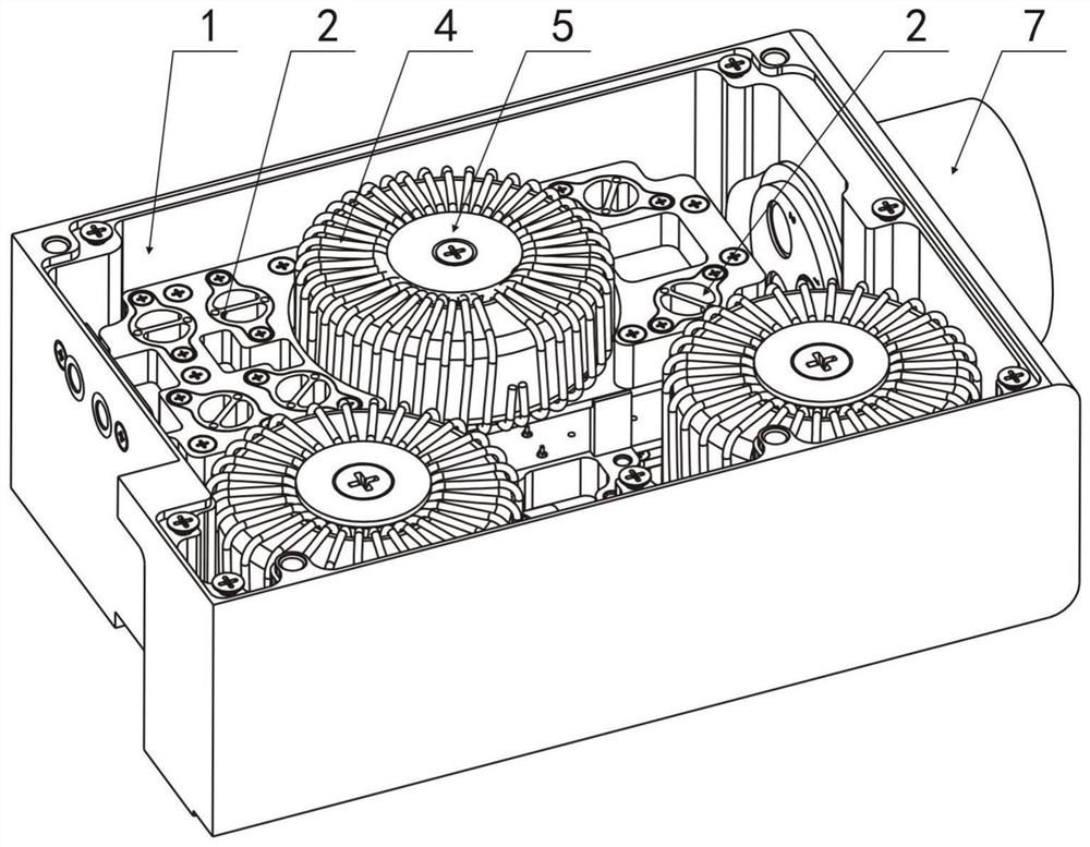
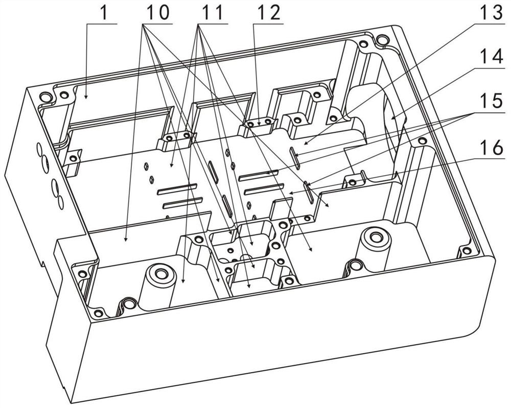
[0042] Such as Figure 1-Figure 7 As shown, the power filter with high-efficiency electromagnetic isolation and high-efficiency heat dissipation functions of the present invention includes a housing 1 and a filter circuit ( Figure 1-Figure 12 The circuit diagram is not shown in the figure), the filter circuit includes interconnected heating devices 31 and annular inductance 4, and the power supply filter also includes a heat sink for cooling the heating devices 31, and is used to weld a plurality of lead wires Connected lead wire welding device 2 and inductance installation device 5 for installing inductance, housing 1 is provided with a plurality of partitions (see the vertical partition 10 and transverse partition 18 in the figure) that are isolated from each other and used to install different The independent inner cavity 11 of the independent device, the heat dissipat...


PUM


Abstract

The invention discloses a power supply filter with high-efficiency electromagnetic isolation and heat dissipation functions. The power supply filter comprises a shell, a filter circuit arranged in theshell, a heat dissipation device, a lead welding device and an inductor mounting device, and is characterized in that the filter circuit comprises a heating device and a circular inductor which are connected with each other; a plurality of independent inner cavities which are isolated from one another through partition plates and used for installing different independent devices are formed in theouter shell, the heat dissipation device comprises heat conduction pieces with high heat conduction coefficients, and the heat conduction pieces are arranged between the corresponding heating devicesand the inner wall of the outer shell and make close contact with the corresponding heating devices and the inner wall of the outer shell respectively. and a plurality of convex radiating fins are arranged in an area, corresponding to the heating device, on the outer wall of the shell. Good electromagnetic shielding effect and high electromagnetic compatibility between electronic components can be realized, independent maintenance of part of the electronic components can also be realized, the use cost is saved, an efficient heat dissipation effect can be realized, and the high-power power supply filter is particularly suitable for high-power power supply filters.

Description

technical field [0001] The invention relates to a power filter mainly used in a motor system, in particular to a power filter with high-efficiency electromagnetic isolation and high-efficiency heat dissipation. Background technique [0002] The power filter is an electrical device that effectively filters the frequency point of a specific frequency in the power line or frequencies other than the frequency point. Its function is to obtain a power signal of a specific frequency or Power signal after removing a specific frequency. [0003] With the increase of application scenarios, power filters put forward higher requirements in terms of electromagnetic compatibility, easy maintenance, and efficient heat dissipation. Traditional power filters are difficult to meet the increasing comprehensive performance requirements. The specific problems are as follows: [0004] The inner cavity of the shell of the traditional power filter is generally an integral inner cavity. In order to...

Claims


Application Information

Patent Timeline
Patent Type & Authority Applications(China)
IPC IPC(8): H05K7/02H05K9/00H05K7/20H02H11/00
CPCH05K7/02H05K9/002H05K7/2039H05K7/20418H02H11/003
Inventor 段晓波唐小辉李瑾计禹钧彭胜勇
Owner CHENGDU HONGMING ELECTRONICS CO LTD
Learn More