
Improved flow cytometer based on optical fiber integrated micro-fluidic chip

A flow cytometer and microfluidic chip technology, applied in the field of cell detection and analysis, can solve the problems of limiting the number of objective lenses used and optical path integration, high requirements for optical path space and stability, complex optical path and spatial structure, etc. Various methods, rich design diversity, and various effects of materials

Pending Publication Date: 2021-01-15
GUILIN UNIV OF ELECTRONIC TECH
View PDF7 Cites 0 Cited by
  • Summary
  • Abstract
  • Description
  • Claims
  • Application Information

AI Technical Summary

Problems solved by technology

They are: flow chamber and liquid flow system; laser source and optical system; photoelectric cell and detection system; computer and analysis system. Module independence, its optical path and space structure are extremely complex, and the manufacturing cost is relatively high
Patent CN111024592A discloses an optical path device of a flow cytometer, the optical path volume is relatively large, and the light receiving structure is relatively complicated
[0007] The traditional flow cytometer uses a spatial optical path, which has high requirements on the spatiality and stability of the optical path, and requires precise adjustment of the optical path, and the optical components are greatly disturbed by external environments such as vibration, temperature, and humidity.
Moreover, these spatial optical components are bulky and the assembly method is not flexible enough
More importantly, the traditional spatial optical path system uses a microscopic objective lens as the light-receiving medium, and the objective lens is large in size, which limits the number of objective lenses used and the integration of optical paths.

Method used


Image

  • Improved flow cytometer based on optical fiber integrated micro-fluidic chip
  • Improved flow cytometer based on optical fiber integrated micro-fluidic chip
  • Improved flow cytometer based on optical fiber integrated micro-fluidic chip

Examples


Embodiment 1

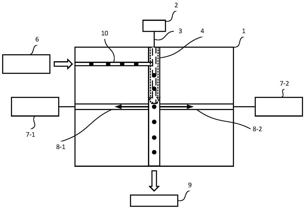
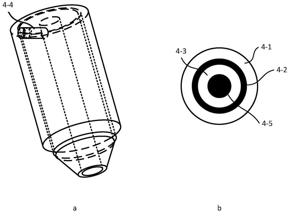
[0035] Such as figure 1 Shown is a system diagram of an improved fiber-integrated microfluidic chip-based flow cytometer. It is composed of five modules: optical fiber integrated microfluidic chip 1, light source 2, fluid control system 6, photoelectric detection system 7, and waste liquid collection system 9. In the system, the fluid control system 6 controls the cell sample and the sheath fluid to form a single cell flow, which flows into the cell flow conduit 10 of the microfluidic chip 1 , and the cell flow conduit 10 is connected with the hollow ring-core optical fiber 4 . The hollow ring-core fiber 4 is connected with the fiber 3 to introduce the excitation light of the light source 2, and the connection mode between the hollow ring-core fiber 4 and the fiber 3 can be in the form of a coupler, such as Figure 8As shown in (a), it can also be in the form of core alignment, such as Figure 8 (b) shown. The hollow ring-core optical fiber 4 uses its own hollow part 4-5 as...

Embodiment 2

[0039] FITC and APC-Cy7 were selected as the markers of cells in the single-cell flow, and the wavelengths of the excitation light were 488nm and 635nm, and the wavelengths of the excited light generated were 530nm and 780nm, respectively.

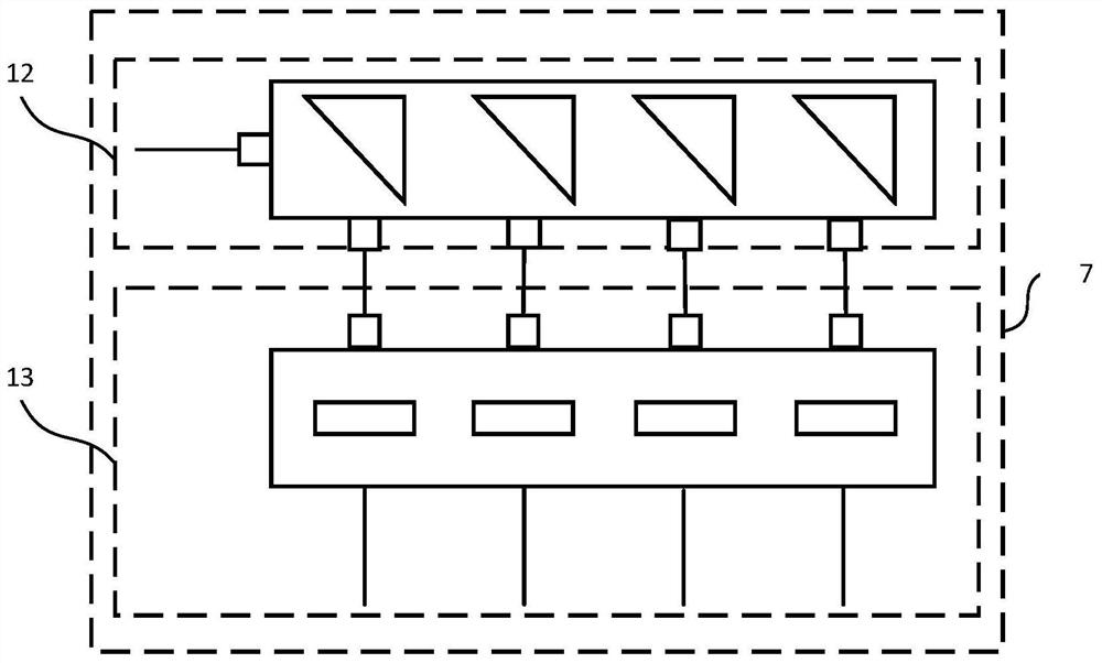
[0040] The light sources 2 - 1 and 2 - 2 are laser light sources of 488nm and 635nm respectively. The light sources are combined by a wavelength division multiplexer 14 , and then transmitted to the hollow ring-core optical fiber 4 via the optical fiber 3 . The cells 11 in the cell flow generate scattered light after being irradiated, and the scattered light is collected by the scattered light collecting optical fibers 8-1 and 8-2, and transmitted to the photoelectric detection systems 7-1 and 7-2 respectively. The scattered light includes light of four wavelengths in total, excitation light with wavelengths of 488nm and 635nm, and excited light with wavelengths of 530nm and 780nm. Take the photoelectric detection system 7-2 as an example ...


PUM


Abstract

The invention provides an improved flow cytometer based on an optical fiber integrated microfluidic chip. The improved flow cytometer is characterized by consisting of five modules, namely an opticalfiber integrated micro-fluidic chip, a light source, a fluid control system, a photoelectric detection system and a waste liquid collection system, in the system, the fluid control system controls a cell sample and sheath fluid to form a cell flow, the cell flow flows into a cell flow conduit of a micro-fluidic chip, the cell flow conduit is connected with a hollow annular core optical fiber, andcells in the cell flow are irradiated by a self-focusing light beam of the hollow annular core optical fiber to generate scattered light. Scattered light collecting optical fibers are embedded in themicro-fluidic chip and are distributed on two sides of the micro-fluidic channel. Scattered signal light in different directions is collected by the optical fiber and transmitted to the photoelectricdetection system for light splitting detection. The improved flow cytometer can be used for analyzing cells.

Description

[0001] (1) Technical field [0002] The invention relates to an improved flow cytometer based on an optical fiber integrated microfluidic chip, which can be used for automatic cell analysis and sorting, and belongs to the technical field of cell detection and analysis. [0003] (2) Background technology [0004] The working principle of flow cytometry is to conduct multi-parameter and rapid quantitative analysis of single cells or other biological particles through monoclonal antibodies at the molecular level. It can analyze tens of thousands of cells at high speed, and can measure multiple parameters from one cell at the same time. It has the advantages of high speed, high precision and good accuracy. It is one of the most advanced cell quantitative analysis technologies in the contemporary era. First used in the 1950s to measure cell volume, it detects cells as they pass in a straight line with a fast-flowing fluid through an observation hole. In a flow cytometer, cells in s...

Claims


Application Information

Patent Timeline
IPC IPC(8): G01N15/14
CPCG01N15/1434G01N2015/144
Inventor 苑立波朱立夫
Owner GUILIN UNIV OF ELECTRONIC TECH
Features
  • Generate Ideas
  • Intellectual Property
  • Life Sciences
  • Materials
  • Tech Scout
  • Unparalleled Data Quality
  • Higher Quality Content
  • 60% Fewer Hallucinations
Learn More