Eureka AIR delivers breakthrough ideas for toughest innovation challenges, trusted by R&D personnel around the world.

Equipment and method for cyclic reaction and continuous separation of magnetic particles in heterogeneous reaction

A technology of magnetic particles and cyclic reactions, applied in chemical instruments and methods, chemical/physical/physicochemical processes using energy, oxidized water/sewage treatment, etc., can solve problems such as increasing costs, not being able to recycle, hindering applications, etc., to achieve Easy operation, high reaction efficiency, exquisite design effect

Pending Publication Date: 2021-01-22
PEKING UNIV
View PDF0 Cites 0 Cited by
  • Summary
  • Abstract
  • Description
  • Claims
  • Application Information

AI Technical Summary

Problems solved by technology

[0003] However, if the nanoparticle catalyst suspended in solution or gas cannot be separated and recovered in time, it will not only greatly increase the cost, but also directly hinder the application.

Method used


Image

  • Equipment and method for cyclic reaction and continuous separation of magnetic particles in heterogeneous reaction
  • Equipment and method for cyclic reaction and continuous separation of magnetic particles in heterogeneous reaction

Examples


Embodiment 1

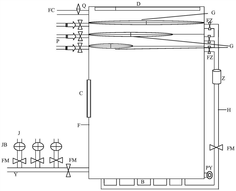
[0034] Such as figure 1As shown, the equipment for circular reaction and continuous separation of magnetic particles in the heterogeneous reaction of this embodiment includes: reactor F, reactant inflow pipeline Y, dosing pipeline J, reactant outflow pipeline FC, outlet PY, Filtration magnetic mesh screen G, jet pump P, branch circuit inlet FZ, loop pipeline H, self-priming pump Z and water distributor pipeline B; wherein, the inside of the reactor F has a closed space; the side outside the reactor F The bottom of the wall is provided with a reactant inflow pipeline Y, which is connected to the inside of the reactor F; three connected dosing pipelines J are arranged on the reactant inflow pipeline Y, and a dosing pump is set on each dosing pipeline J JB; a reactant outflow pipeline FC is provided on the top of the sidewall outside the reactor F, and is connected to the inside of the reactor F; a discharge port PY is provided at the bottom of the sidewall of the reactor F oppos...

Embodiment 2

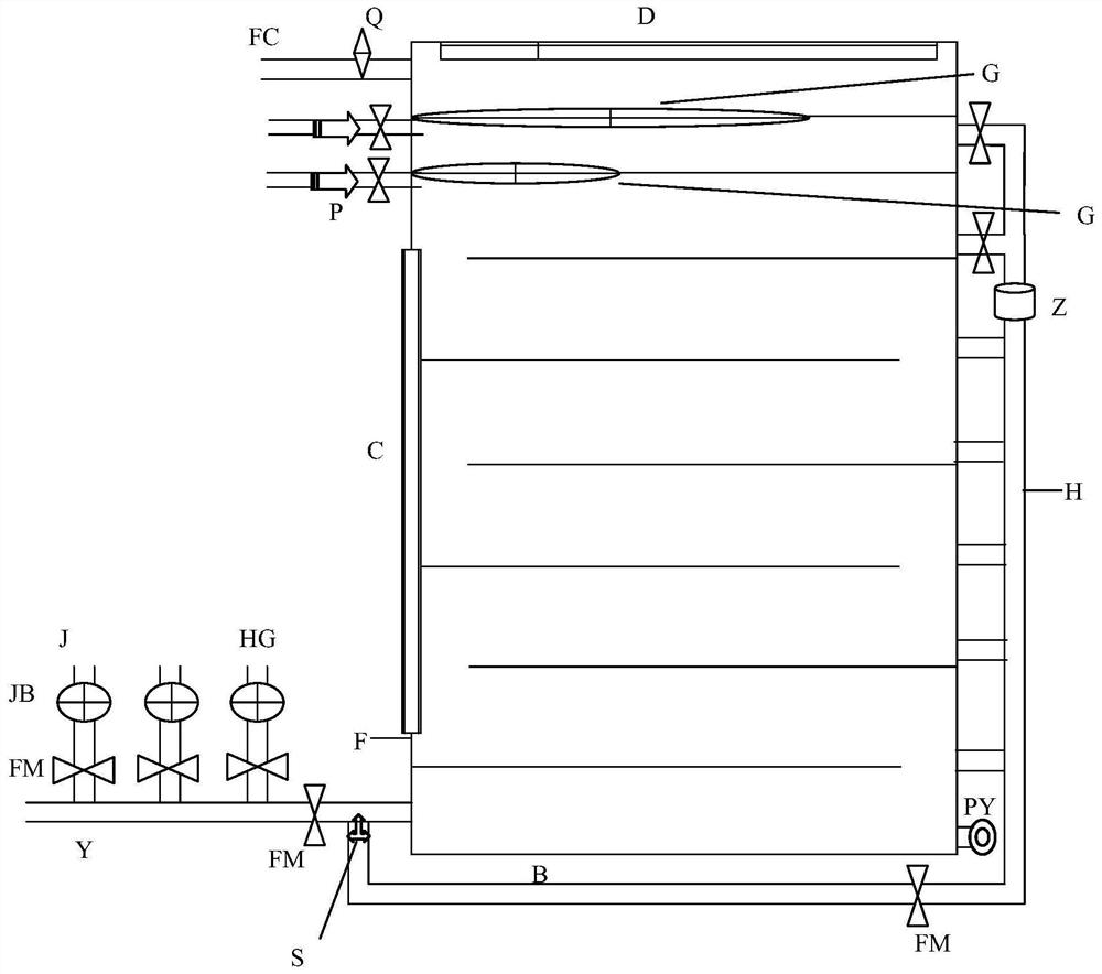
[0045] Such as figure 2 As shown, in this embodiment, the flow rate of the liquid inlet is fast, and the fluid is turbulent; in the reactor F, the partitions are placed horizontally at equal intervals from bottom to top, and the area of ​​the partitions is smaller than the horizontal area of ​​the internal space of the reactor F. The plates are arranged in a staggered manner, that is, the partitions are alternately connected with the side walls of one side, thereby forming a serpentine channel in the reactor F; the liquid inlet speed is very fast, and the length of the liquid flow channel is increased through the serpentine channel, thereby To ensure a long reaction time; corresponding to each layer of partitions, a branch circuit outlet is provided, each branch circuit outlet is connected to the circuit pipeline under the self-priming pump, and the branch circuit outlet will suspend the reaction of magnetic particles The final fluid is transported back to the reactor to keep...


PUM


Abstract

The invention discloses equipment and a method for cyclic reaction and continuous separation of magnetic particles in heterogeneous reaction. A filtering magnetic mesh screen is arranged in a reactor,is made of a magnetic material and is provided with meshes; injection pump branch loops are respectively arranged on two side walls, opposite to the filtering magnetic mesh screen, outside the reactor, the branch loops are combined and communicated to a loop pipeline, and a self-priming pump is arranged on the loop pipeline; the magnetic particles suspended in the reactants rise to the filteringmagnetic mesh screen along with the fluid and are adsorbed by the filtering magnetic mesh screen; the jet pump and the self-priming pump are opened, the fluid impact force separates the magnetic particles from the filtering magnetic mesh screen, the magnetic particles are brought into the branch loop by the fluid suction force of the self-priming pump, and then the magnetic particles flow back tothe reactor from the bottom through the loop pipeline. According to the invention, a continuous reaction system flow path and an intermittent reaction flow path are adopted, such that a solid-phase catalyst circulation reaction is realized. The equipment is ingenious in design, easy and convenient to operate and high in reaction efficiency; the equipment is applied to treatment of organic wastewater by an advanced oxidation technology.

Description

technical field [0001] The invention relates to chemical and chemical reaction technology, in particular to a device for circular reaction and continuous separation of magnetic particles in a heterogeneous reaction and a realization method thereof. Background technique [0002] Due to its unique small size effect, surface characteristics and various excellent physical and chemical properties, nanomaterials have a wide range of application prospects. Because of its large specific surface area and high surface activity, nanoparticle catalysts are catalysts with excellent performance. Especially when nanoparticle catalysts are distributed in solution or gas and applied in suspension, they can participate in chemical reactions more efficiently. [0003] However, if the nanoparticle catalysts suspended in solution or gas cannot be separated and recovered in time, not only will the cost be greatly increased, but also the application will be directly hindered. No matter how good t...

Claims


Application Information

Patent Timeline
Patent Type & Authority Applications(China)
IPC IPC(8): B01J8/34B01J19/10B01J19/12C02F1/72C02F101/30
CPCB01J8/005B01J8/006B01J8/1854B01J8/34B01J19/10B01J19/123C02F1/722C02F1/725C02F2101/30C02F2305/026
Inventor 王岩吕明泉马艳子徐烜峰李国宝
Owner PEKING UNIV
Why Eureka
Eureka Blog
Learn More