Micro-turbine for turbine generator and air guide structure size calculation method thereof

A technology of turbine generator and wind guide structure, which is applied in the direction of wind power generators, calculations, engines, etc., which is consistent with the wind direction, can solve the problems of not being able to fully expand the air volume, not being able to make full use of wind energy, and the height of the turbine blades being low. The effect of increasing power, increasing power, and reducing loss

Pending Publication Date: 2021-01-22
芜湖博高光电科技股份有限公司
View PDF0 Cites 0 Cited by
  • Summary
  • Abstract
  • Description
  • Claims
  • Application Information

AI Technical Summary

Problems solved by technology

[0003] The wind coming from the front part corresponds to the normal line of the turbine because the wind speed vector is right, and part of the wind returns, resulting in serious wind energy loss
[0004] The height of the existing turbine wind blades is low, and the interface of the air duct is small, which cannot fully expand the air intake volume, causing eddy currents to form on the air duct, and then cannot make full use of wind energy, greatly reducing the power generation efficiency of the turbine

Method used


Image

  • Micro-turbine for turbine generator and air guide structure size calculation method thereof
  • Micro-turbine for turbine generator and air guide structure size calculation method thereof
  • Micro-turbine for turbine generator and air guide structure size calculation method thereof

Examples


Embodiment 1

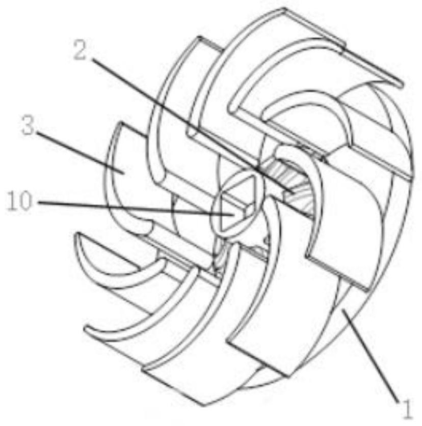
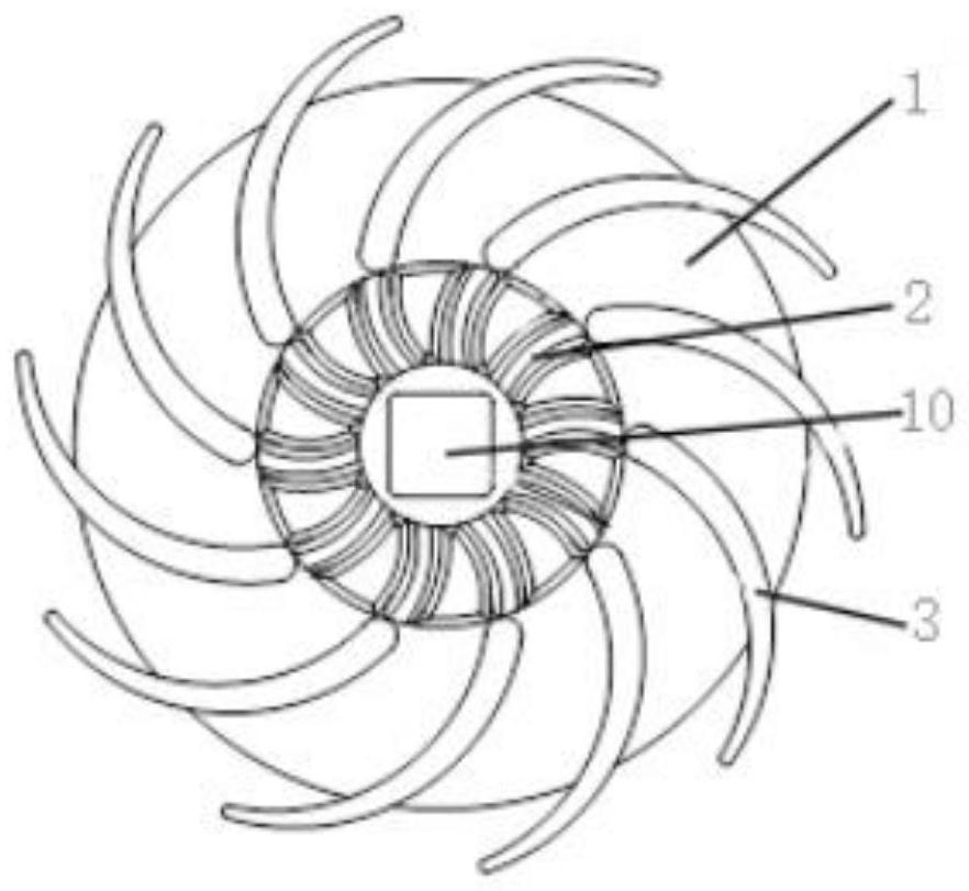
[0109] The micro-turbine for the turbo generator, the wind guide structure 2 is arranged inside the bottom support platform 1, the described wind guide structure 2 is a plurality of curved reinforcing ribs, and the wind blade 3 is arranged outside the bottom support platform 1, so The wind guide structure 2 and the wind blade 3 transition smoothly; the wind guide structure 2 is evenly distributed along the circumference of the bottom support platform 1, and the wind blade 3 is evenly distributed along the circumference of the bottom support platform 1; The upper end of the wind structure 2 is provided with rounded corners to reduce the amount of reflected air, and the start-up wind speed is lower, which can reduce the start-up wind speed by more than 3m / s. In addition, the wind guide structure 2 and the wind blade 3 smoothly transition, and the direction of the wind is dredged, reducing The wind resistance increases the wind force rushing towards the wind blade 3, thereby reduc...

Embodiment 2

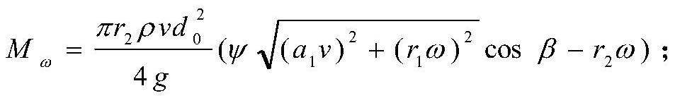
[0111] The method for calculating the size of the wind guide structure of the micro-turbine used in the turbogenerator can be seen from the comprehensive analysis of the above formulas, in order to increase the output voltage of the turbogenerator, the E d 、X aq value, reduce the internal resistance value r of the turbine generator. But E d 、X aq The value is related to the frequency of the turbine generator, the number of winding turns and the no-load effective flux factor. These factors are directly proportional to the output frequency of the turbine generator. Therefore, increasing the speed of the turbine generator is the most effective way to increase the output voltage of the turbine generator. However, when the speed of the turbine generator increases to a certain level, the output voltage of the turbine generator will not increase linearly, but tends to be flat due to the increase of the armature reaction and the hysteresis loss of the magnetic circuit. Based on t...


PUM


Abstract

The invention discloses a micro-turbine for a turbine generator and an air guide structure size calculation method thereof. The micro-turbine for the turbine generator comprises a bottom supporting table, an air guide structure and blades, wherein the bottom supporting table is of a disc structure, a shaft hole is formed in the center of the bottom supporting table, the air guide structure is arranged in the bottom supporting table, and the air guide structure is composed of a plurality of bent reinforcing ribs; The blades are arranged outside the bottom supporting table. The air guide structure and the blades are in smooth transition, so that the reflection air volume is reduced, and the start-up air speed is lower and can be lowered by more than 3m/s; and the wind direction is guided, the wind resistance is reduced, the wind force rushing to the blades is increased, so that the loss of wind energy is reduced, and the power of the turbine generator is improved by more than 5%.

Description

technical field [0001] The invention belongs to the technical field of power generation equipment. Specifically, the invention relates to a method for calculating the dimensions of a microturbine and an air guiding structure for a turbogenerator. Background technique [0002] At present, the windward platform of the radial flow turbine in the turbogenerator we use is a planar structure, and its disadvantages are: [0003] Because the wind speed vector from the front is corresponding to the normal of the turbine, part of the wind force returns, resulting in serious loss of wind energy. [0004] The height of the blades of the existing turbines is low, and the interface of the air duct is small, which cannot fully expand the air intake volume, causing eddy currents to form on the air duct, and then cannot make full use of wind energy, greatly reducing the power generation efficiency of the turbine. Contents of the invention [0005] The present invention provides a method f...

Claims


Application Information

Patent Timeline
Patent Type & Authority Applications(China)
IPC IPC(8): F03D1/06F03D9/25G06F30/17G06F113/06G06F119/06
CPCF03D1/0625F03D1/0633F03D1/0691F03D9/25G06F30/17G06F2113/06G06F2119/06Y02E10/72
Inventor 苏刚刘永明刘同海刘成虎高书乾王斌张盼
Owner 芜湖博高光电科技股份有限公司
Why Eureka
Try Eureka