Scanning flow type cell imaging analyzer

A flow cytometry and analyzer technology, which is applied in the analysis of materials, individual particle analysis, particle and sedimentation analysis, etc., can solve the problems of uneven Gaussian distribution of laser spots, decreased imaging quality, and decreased imaging accuracy, and can overcome the problem of spot power. Effects of uneven excitation, improved clarity and precision, and elimination of spherical and chromatic aberrations

Pending Publication Date: 2021-01-22
SUZHOU INST OF BIOMEDICAL ENG & TECH CHINESE ACADEMY OF SCI
View PDF0 Cites 5 Cited by
  • Summary
  • Abstract
  • Description
  • Claims
  • Application Information

AI Technical Summary

Problems solved by technology

However, the image of each point on the field light source target will be interfered by the diffraction or scattered light of adjacent points, resulting in a decline in imaging quality. In addition, the uneven Gaussian distribution of the laser spot and the disturbance of the liquid flow system will further cause a decrease in imaging accuracy.

Method used


Image

  • Scanning flow type cell imaging analyzer
  • Scanning flow type cell imaging analyzer
  • Scanning flow type cell imaging analyzer

Examples


Embodiment 1

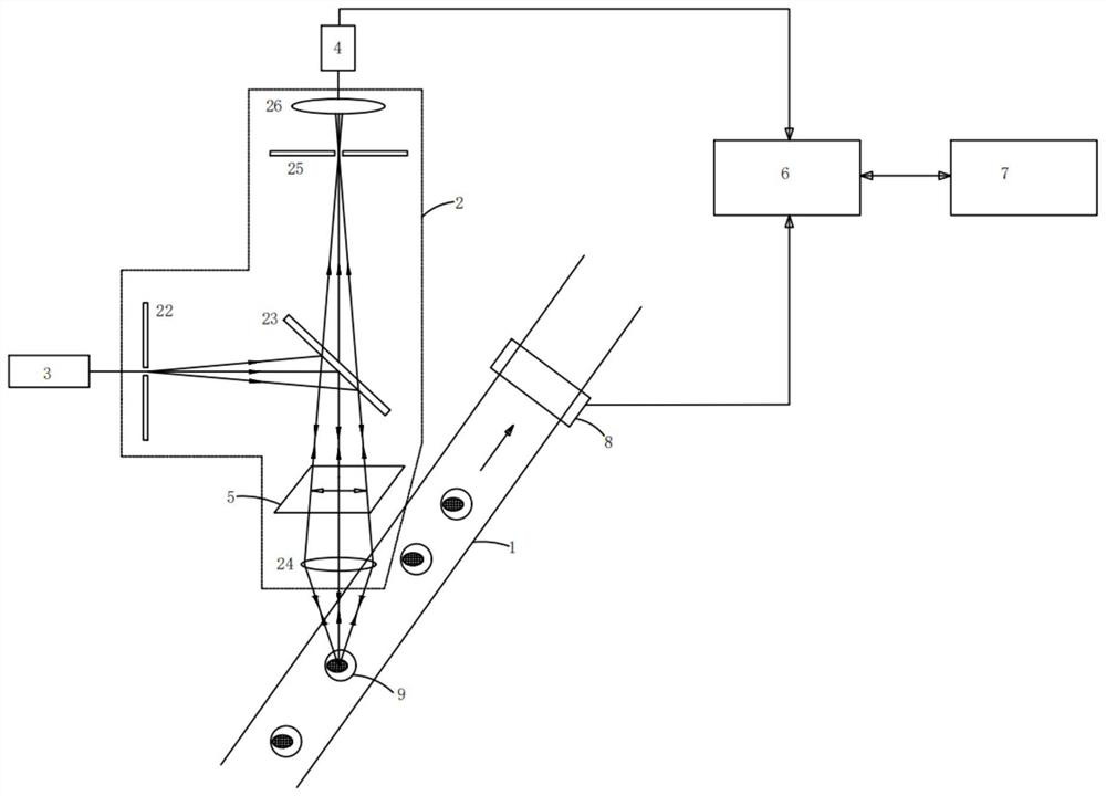
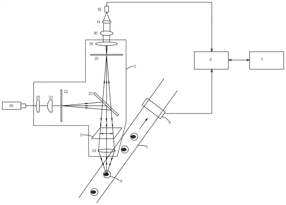
[0057] refer to figure 1 and image 3 , in this embodiment, the optical signal excitation detection module includes a main optical path unit 2, a set of laser emitting optical paths 3, and a set of optical signal detection optical paths 4 corresponding to the laser emitting optical paths 3;

[0058] The laser emitting optical path 3 generates laser light and transmits it to the main optical path unit 2. The main optical path unit 2 forms a laser spot and focuses it on the particles or cells 9 in the detection area. The main optical path unit 2 also collects the fluorescence and The scattered light is transmitted to the optical signal detection optical path 4, and the optical signal detection optical path 4 collects fluorescence and scattered light signals, converts them into electrical signals, and transmits them to the acquisition and control board 6.

[0059] Wherein, the main optical path unit 2 includes an excitation pinhole 22, a first dichroic mirror 23, and an objectiv...

Embodiment 2

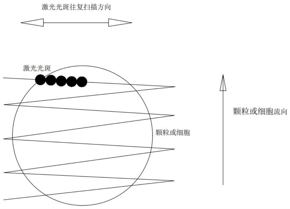
[0069] refer to Figure 4-6 , as a further improvement on the basis of Embodiment 1, in this embodiment, the laser emission optical path 3 and the optical signal detection optical path 4 can be expanded into multiple groups, and when multiple lasers are used, multiple laser points can be used at the same point or multiple laser points can be separated by a certain space distance; at this time, the corresponding detection pinhole 25 also presents a certain spatial arrangement, corresponding to the multi-channel laser one by one; refer to Figure 4 , it needs to be understood that from Figure 4 The three laser beams are superimposed in the direction of the direction, but in fact they are not coincident, there is a certain distance, and this distance is reflected in another direction: that is, the direction perpendicular to the paper.

[0070] In this embodiment, the number of laser emitting optical paths 3 is N, and N is greater than 1. The laser emitting optical path 3 also i...

Embodiment 3

[0075] refer to Figure 7 , as a further improvement on the basis of Embodiment 1 or Embodiment 2, in this embodiment, the scanning galvanometer 5 includes a bracket 50 with an opening in the middle, and is suspended in the opening of the bracket 50 by two symmetrically distributed elastic arms 51 The reflective sheet 52 and the piezoelectric sheet 54 arranged on the side arm 53 of the support 50 are used to generate an inverse piezoelectric effect under the action of an electric field, thereby driving the reflective sheet 52 to twist and rotate. In this embodiment, a mounting piece 55 is also provided on the bracket 50 . The smaller the size of the scanning vibrating mirror 5 , the higher the attainable scanning frequency. For scanning above MHz, a micron-scale vibrating mirror can be manufactured by using MEMS technology.


PUM


Abstract

The invention discloses a scanning flow type cell imaging analyzer. The scanning flow type cell imaging analyzer comprises a liquid flow focusing module, an optical signal excitation detection module,a scanning galvanometer, an acquisition and control board card and an upper computer. Laser is focused into light spots smaller than cells in size, cell imaging is achieved through light spot scanning, the power density of an imaging light source can be improved, and fluorescence is effectively excited; when a scanning excitation mode is adopted, laser full light spots are used for imaging, an overall excitation effect is achieved, and the situation of uneven distribution does not exist; and meanwhile, a problem that the imaging quality is reduced due to non-uniform excitation of light spot power caused by unstable liquid flow can be solved. According to the invention, the detection pinhole is formed in the focal plane of the objective lens, so that stray light outside the focal plane canbe blocked, and spherical aberration and chromatic aberration are eliminated; a photomultiplier is adopted to collect optical signals, and weak signals can be amplified; and compared with a traditional CCD imaging sensitivity, the sensitivity is greatly improved.

Description

technical field [0001] The invention relates to the technical field of biological particle detection, in particular to a scanning flow cytometry imaging analyzer. Background technique [0002] Flow cytometry is a technique that can quickly quantitatively analyze and sort cells or other biological particles that are arranged in a single file in a liquid flow. Compared with traditional flow cytometers, imaging flow cytometers have greater advantages when it is necessary to obtain cell morphology and internal structure information. It combines the high throughput of the flow cytometry system with the subcellular resolution of the imaging system, which not only makes up for the inability of traditional flow cytometry to distinguish subcellular structural features and morphological information, but also improves the imaging rate of the optical microscopic imaging system. The disadvantage caused by low is not suitable for large-scale cell observation. The fine morphological info...

Claims


Application Information

Patent Timeline
Patent Type & Authority Applications(China)
IPC IPC(8): G01N15/14
CPCG01N15/1425G01N15/1434G01N15/1484G01N2015/144G01N2015/1479G01N2015/1481
Inventor 马玉婷裴智果王策陈忠祥吴云良宋飞飞钟金凤严心涛王耀
Owner SUZHOU INST OF BIOMEDICAL ENG & TECH CHINESE ACADEMY OF SCI
Why Eureka
Try Eureka