Method for manufacturing implantable micro-biosensor

A manufacturing method and micro-biological technology, which can be applied in sensors, medical science, catheters, etc., can solve the problems of high infection risk, large implantation wound, and significant pain, so as to reduce the influence of interfering substances, measure accuracy, and meet the requirements of the manufacturing process. Effect

Pending Publication Date: 2021-02-02
BIONIME
View PDF0 Cites 0 Cited by
  • Summary
  • Abstract
  • Description
  • Claims
  • Application Information

AI Technical Summary

Problems solved by technology

However, in order to avoid implanting deep into the subcutaneous tissue, these biosensors need to be implanted at an oblique angle

Method used


Image

  • Method for manufacturing implantable micro-biosensor
  • Method for manufacturing implantable micro-biosensor
  • Method for manufacturing implantable micro-biosensor

Examples


Embodiment 1

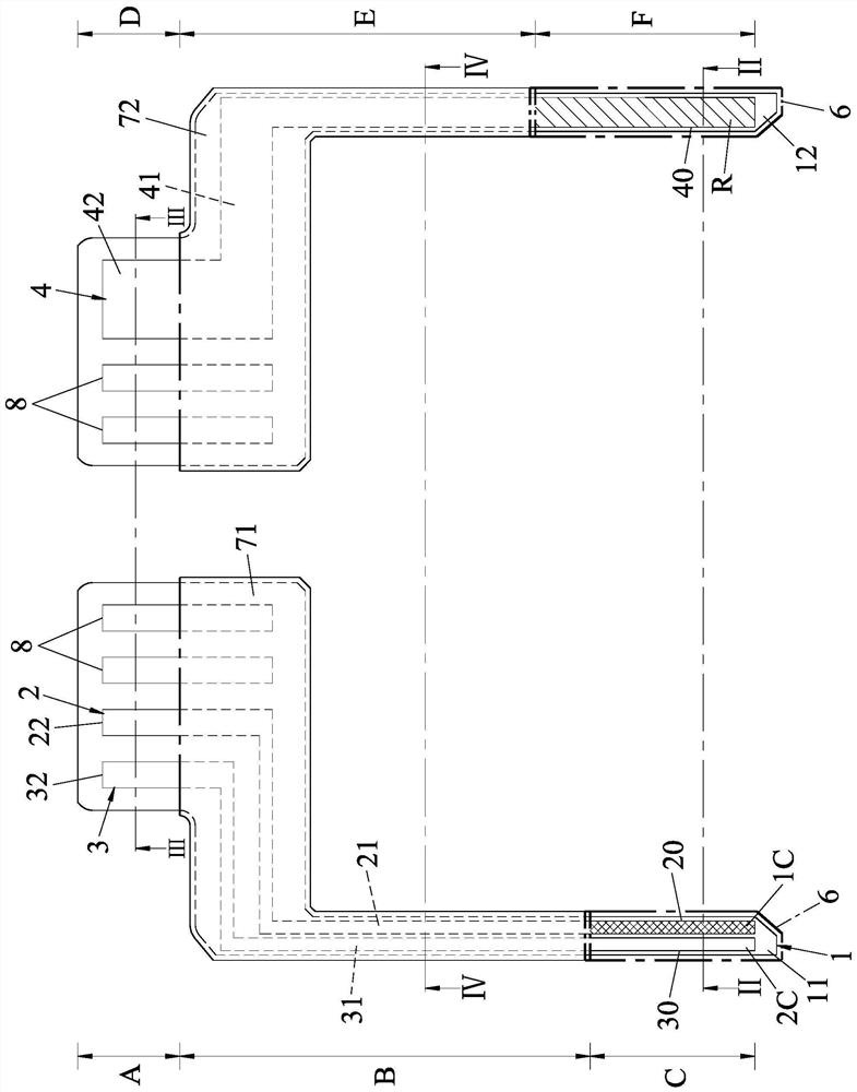
[0097] figure 1 It is a schematic structural diagram of the implantable miniature biosensor of Example 1 of the present invention. In Embodiment 1, the first surface of the implanted miniature biosensor is divided into a first signal output area A for connecting with a transmitter (not shown in the figure), and an area A for measuring the analyte in the organism. A first sensing region C for a physiological parameter (such as concentration, glucose concentration in embodiment 1) and a first signal connection region B connecting the first signal output region A and the first sensing region C. The implantable miniature biosensor is partially implanted under the skin surface of the organism in a manner perpendicular to the skin surface of the organism and has an implant end, and the implant end at least includes the first sensing region c. Specifically, the length of the implant end must at least reach the dermis and measure the depth of glucose in the interstitial fluid, and i...

Embodiment 2

[0131] Please refer to Figure 16 to Figure 19 , the structure of the implantable miniature biosensor of embodiment 2 is roughly the same as that of embodiment 1, the difference is that: in order to effectively reduce the interference of the interfering substance to the measurement of the physiological signal within an error range, the second embodiment of embodiment 2 The two sensing sections 30 are adjacent to at least three sides of the first sensing section 20 with a gap, that is, the second sensing section 30 surrounds at least three sides of the first sensing section 20 with the gap. side. Preferably, the gap is not greater than 0.2mm, but more preferably the gap ranges from 0.02mm to 0.05mm. More specifically, one side of the second sensing section 30 extends along the periphery of the first sensing section 20 and is bent to surround at least three sides of the first sensing section 20 in a U shape. At this time, if Figure 20 As shown, the second sensing section 30 ...

Embodiment 3

[0135] Such as Figure 24 to Figure 26 As shown, the structure of the implantable micro-biosensor of embodiment 3 is substantially the same as that of embodiment 2, the difference is that the implantable micro-biosensor of embodiment 3 also includes a pair of electrodes 4 spaced apart from each other. The reference electrode 9 on the second surface 12, and the surface of the reference electrode 9 contains at least silver / silver halide R. In order to provide sufficient capacity and adjust the amount of silver / silver halide, the area of ​​the counter electrode 4 is larger than that of the reference electrode 9 .

[0136] To elaborate further, such as Figure 24 As shown, the pair of electrodes 4 is specifically arranged on the second surface 12 of the substrate 1 and is designed in the second sensing region F of the implanted end of the implantable micro biosensor to have an electrode along the implantation direction. (that is, the direction perpendicular to the skin surface o...


PUM


Abstract

A method for manufacturing an implantable micro-biosensor includes the steps of: providing a substrate with a first sensing area on one surface, forming on one surface of the substrate a first workingelectrode which at least includes a first sensing section including a first conductive material, forming on one surface of the substrate at least one second working electrode which at least includesa second sensing section disposed proximate to at least one side of the first sensing section, and forming a chemical reagent layer which at least covers the first conductive material of the first sensing section and which reacts with the analyte to produce a product. The method can be used for manufacturing two sensing sections with different surface materials in the same sensing area, can precisely control the shape, size and position of the electrode through a patterning process, and can meet the requirements of simplification of the manufacturing process.

Description

technical field [0001] The invention relates to a method for manufacturing a biosensor, in particular to a method for manufacturing an implanted miniature biosensor. Background technique [0002] The population of diabetic patients is growing rapidly, and there is an increasing emphasis on the need to monitor the changes in glucose (Glucose) in the body. Therefore, many studies have begun to develop a system that can be implanted in the body for continuous glucose monitoring (CGM) to solve the daily needs. Repeated blood collection and testing bring inconvenience to the life of patients. The basic structure of the continuous glucose monitoring system includes a biosensor (Biosensor) and a transmitter (Transmitter). The biosensor is used to measure the physiological signal corresponding to the glucose concentration in the body, and most of them use electrochemical methods, that is, glucose oxidase (glucose oxidase, GOx) catalyzes the reaction of glucose to generate gluconola...

Claims


Application Information

Patent Timeline
IPC IPC(8): A61B5/1473
CPCA61B5/14503A61B5/14532A61B5/14546A61B2562/164A61B2562/225A61B2562/125A61B5/1451A61B5/14865A61B5/1473Y10T29/49002Y10T29/49826
Inventor 黄椿木陈界行张恒嘉陈继浩陈建中
Owner BIONIME
Why Eureka
Try Eureka