Bending blade, thread clipper with blade and blade manufacturing method
A blade and bending technology, applied in the field of bending blades, yarn scissors with the blade and blade manufacturing, can solve problems such as reduced efficiency, and achieve the effects of reducing grinding area, high efficiency, and reducing surface roughness
- Summary
- Abstract
- Description
- Claims
- Application Information
AI Technical Summary
Problems solved by technology
Method used
Image
Examples
Embodiment 1
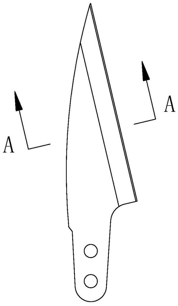
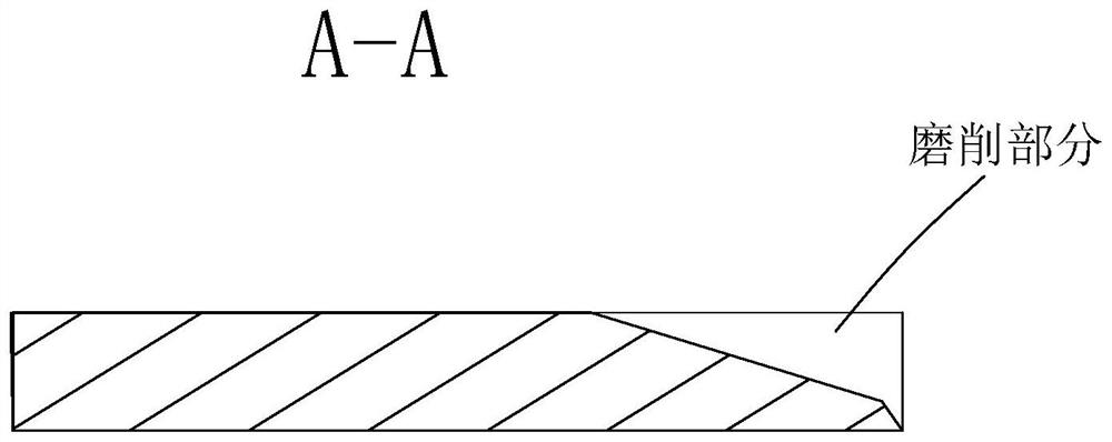
[0055] Such as Figure 4-6 As shown, a bending blade is characterized in that: it includes a blade body 1 for installation and fixed connection with the handle 4, a bending part connected to one edge of the blade body 1 and bent relative to the plane where the blade body 1 is located 2 and the cutting edge 3 arranged on the outer edge line of the bent portion 2 away from the blade body 1, the thickness L of the blade body 1 and the bent portion 2 is: 0.5-0.9 mm.
[0056] Preferably, the thickness L of the blade body 1 and the bent portion 2 is 0.7mm.
[0057] Preferably, the angle α between the inner surface of the bent portion 2 and the plane where the blade body 1 is located is: 150°-170°. The inner surface is the mating surface when the two bent blades cooperate with each other to cut.
[0058] Preferably, the angle α between the inner surface of the bent portion 2 and the plane where the blade body 1 is located is 160°.
[0059] Preferably, the bending blade is formed b...
Embodiment 2
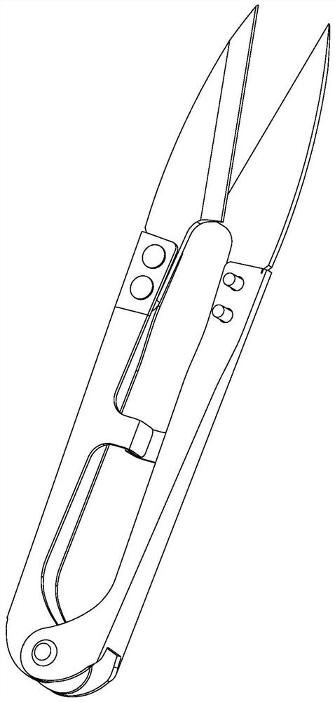
[0065] Such as Figure 4-9 As shown, a yarn cutter with the bending blade described in Embodiment 1 is characterized in that: it also includes a handle 4, and the handle 4 includes two pressing arms 41 arranged at intervals and connected to the two pressing arms 41 The elastic return section 42 between the lower ends;
[0066] Each pressing arm 41 is provided with a mounting portion at one end away from the elastic reset section 42, and the number of the bending blades is two pieces and are respectively fixedly installed on the mounting portions of the two pressing arms 41, and the blade of each bending blade The mouth 3 points to the side where the other bending blade is located, and the inner surface of each bending blade faces the inner surface of the other bending blade;
[0067] When the pressing arm 41 of the movable pressing handle 4 makes the two pressing arms 41 approach each other, it can drive the two bending blades to carry out cooperative shearing, and when the a...
Embodiment 3
[0079] Such as Figure 4-6 10, a method of manufacturing the bending blade described in Embodiment 1 is characterized in that: comprising the following steps:
[0080] ①Blanking: place the steel strip on the punching machine, and punch out the positioning hole 11, the oblique slot 12 of each bending blade and the edge scrap 5 between two adjacent bending blades along the length direction of the steel strip , the edge scrap 5 is arranged obliquely relative to the length direction of the steel strip, and then the steel strip is bent to form the blade body 1 and the bending portion 2 of each bending blade, and finally according to the shape of each bending blade on the steel strip Creases on the belt that emboss the outer contour of each bent blade;
[0081] ②Heat treatment: send the steel strip punched in step ① into the quenching furnace for heat treatment, so that the steel strip can meet the hardness requirement;
[0082] ③Edge sharpening: Send the steel strip after the hea...
PUM
 Abstract
Description
Claims
Application Information
 - R&D
- Intellectual Property
- Life Sciences
- Materials
- Tech Scout
- Unparalleled Data Quality
- Higher Quality Content
- 60% Fewer Hallucinations
Browse by: Latest US Patents, China's latest patents, Technical Efficacy Thesaurus, Application Domain, Technology Topic, Popular Technical Reports.
© 2025 PatSnap. All rights reserved.Legal|Privacy policy|Modern Slavery Act Transparency Statement|Sitemap|About US| Contact US: help@patsnap.com


