Chain grate and rotary kiln pellet roasting flue gas denitration process

A technology of grate machine and rotary kiln, which is applied in the field of waste gas treatment and can solve the problems of stable operation of flue gas denitrification and knocking

Inactive Publication Date: 2021-02-02
SHANDONG SHIHENG SPECIAL STEEL GROUP
View PDF5 Cites 3 Cited by
  • Summary
  • Abstract
  • Description
  • Claims
  • Application Information

AI Technical Summary

Problems solved by technology

[0003] The problems exposed in the current operation of coking and sintering flue gas...

Method used


Image

  • Chain grate and rotary kiln pellet roasting flue gas denitration process

Examples


Embodiment Construction

[0024] The technical solutions of the present invention will be further described below through specific embodiments. It should be clear to those skilled in the art that the embodiments are only for helping to understand the present invention, and should not be regarded as specific limitations on the present invention.

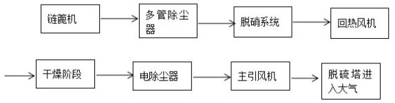
[0025] A chain grate-rotary kiln pellet roasting flue gas denitrification process, the process includes a chain grate, a multi-pipe dust collector, a denitrification system, a heat recovery fan, a drying stage, an electric dust collector, a main induced draft fan, and a desulfurization tower.

[0026] The denitrification system includes an SCR part and a combustion heat supplement part. A hot blast stove system is installed in front of the multi-tube dust collector to stabilize the flue gas temperature at 320~350°C.

[0027] The fuel used in the hot stove system is coke oven gas. The denitrification system adopts medium-high temperature SCR flue gas denitrif...


PUM


Abstract

The invention relates to a chain grate and rotary kiln pellet roasting flue gas denitration system and method. The chain grate and rotary kiln pellet roasting flue gas denitration system can reasonably utilize the heat of the chain grate and rotary kiln flue gas, and nitrogen oxide in the flue gas is removed according to the nitrogen oxide generation mechanism. Therefore, the purpose of removing nitric oxide in the flue gas is achieved.

Description

technical field [0001] The invention belongs to the technical field of waste gas treatment, and in particular relates to a chain grate-rotary kiln pellet roasting flue gas denitrification process. Background technique [0002] In recent years, with the emergence of environmental problems, the state and local governments have paid more and more attention to environmental protection, and the emission standards have been continuously improved. The ultra-low emission of the iron and steel industry has become the focus of the country after the ultra-low emission of the power industry. The control of nitrogen oxides Especially powerful. Medium and high temperature SCR flue gas denitrification technology is widely used, but there are few successful cases of high temperature flue gas denitrification technology in pelletized SCR, and there is not much experience to learn from. [0003] The problems exposed in the current operation of coking and sintering flue gas denitrification hav...

Claims


Application Information

Patent Timeline
IPC IPC(8): F27D17/00F23G7/07
CPCF23G7/07F23G2209/14F27D17/008
Inventor 石志新刘光峰梁春明刘刚李建磊张谦
Owner SHANDONG SHIHENG SPECIAL STEEL GROUP
Why Eureka
Try Eureka