Real-time fluorescence detection optical system and real-time fluorescence quantitative PCR instrument

A fluorescence detection and optical system technology, which is applied in the field of medical inspection and testing instruments and molecular diagnostic testing instruments, to achieve the effects of easy assembly and installation, small size, and improved detection efficiency

Active Publication Date: 2021-02-02
SUZHOU MOLARRAY CO LTD
View PDF20 Cites 7 Cited by
  • Summary
  • Abstract
  • Description
  • Claims
  • Application Information

AI Technical Summary

Problems solved by technology

[0013] Through the above analysis, it can be seen that the multi-channel fluorescence detection optical system of Embodiment 1-4 limits the number of channels in its structure, that is, it only meets the design of no more than 4 channels. For 5 channels, 6 channels, 7 channels, and 8 channels situation, it is not possible to satisfy

Method used


Image

  • Real-time fluorescence detection optical system and real-time fluorescence quantitative PCR instrument
  • Real-time fluorescence detection optical system and real-time fluorescence quantitative PCR instrument
  • Real-time fluorescence detection optical system and real-time fluorescence quantitative PCR instrument

Examples


Embodiment 1

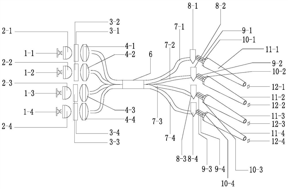
[0074] Embodiment 1, refer to figure 1 As shown, a 4-reagent well (reaction cell) 4-channel fluorescence detection optical system, including: four kinds of single-color LEDs:

[0075] The first LED lamp 1-1, the second LED lamp 1-2, the third LED lamp 1-3, the fourth LED lamp 1-4, the first collimating lens 2-1, the second collimating lens 2-1, The third collimating lens 2-1, the fourth collimating lens 2-4, the first excitation light system filter 3-1, the second excitation light system filter 3-2, the third excitation light system filter 3-3, the fourth excitation light system filter 3-4, the first focusing lens 4-1, the second focusing lens 4-2, the third focusing lens 4-3, the fourth focusing lens 4-4, the first Launch fiber 5-1, second launch fiber 5-2, third launch fiber 5-2, fourth launch fiber 5-4, plastic light guide rod 6, fifth launch fiber 7-1, sixth launch fiber 7- 2. The seventh emitting optical fiber 7-3, the eighth emitting optical fiber 7-4, the first react...

Embodiment 2

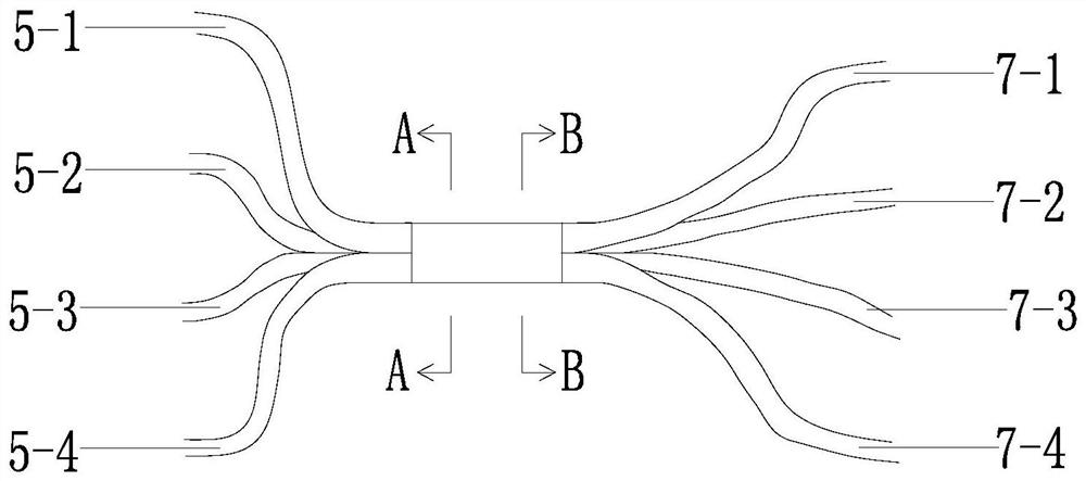
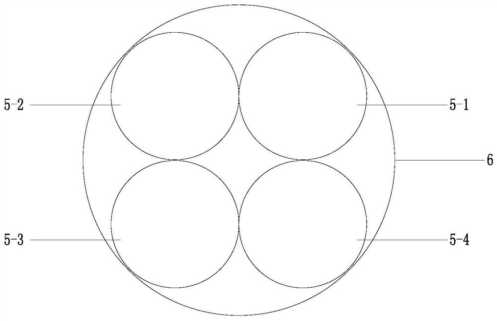
[0112] Embodiment two, such as Figure 7 As shown, a more general scheme, a fluorescent detection optical system with N reagent holes and M channels, where M and N are both natural numbers, includes: M channel components, plastic light guide rods, and N reagent hole detection components;

[0113] Wherein, the M channel assembly includes: M single-channel assemblies; the single-channel assembly includes: a monochromatic LED lamp, a collimating lens, an excitation light system filter, a focusing lens, and an emission fiber; the front of the monochromatic LED lamp A collimating lens is provided, an excitation light system filter is arranged in front of the collimation lens, a focusing lens is arranged in front of the excitation light system filter, and a launching optical fiber is arranged in front of the focusing lens;

[0114] Wherein, the N reagent well detection assembly includes: N single reagent well detection assemblies; each single reagent well detection assembly includes...


PUM


Abstract

The invention discloses a fluorescence detection optical system, and a real-time fluorescence quantitative PCR instrument, which belong to the field of molecular diagnosis detectors. The technical keypoints are as follows: the M-channel assembly comprises M single-channel assemblies; the single-channel assembly comprises a single-color LED lamp, a collimating lens, an exciting light system optical filter, a focusing lens and a transmitting optical fiber. The N reagent hole detection assemblies comprise N single reagent hole detection assemblies; each single reagent hole detection assembly comprises a transmitting optical fiber, a reaction tank, a receiving optical fiber assembly, a receiving end optical filter assembly, a conical light guide rod and a photoelectric sensor; the transmitting optical fiber of each single-channel assembly of the M-channel assembly is connected to the first end of the plastic light guide rod; and each single reagent hole detection assembly of the N reagenthole detection assemblies comprises a transmitting optical fiber which is connected to the second end of the plastic light guide rod. The invention aims to provide a fluorescence detection optical system and a real-time fluorescence quantitative PCR instrument, and the detection efficiency is greatly improved.

Description

technical field [0001] The present invention relates to the field of a medical inspection instrument and a molecular diagnostic detection instrument, and more specifically relates to a fluorescence detection optical system and a real-time fluorescence quantitative PCR instrument. Background technique [0002] Fluorescence detection, which can be used to detect cells, bacteria, molds, etc., is an important detection method. In "Li Chen et al., A Review of Biochip Fluorescence Detection Optical Systems, Optical Instruments, 2005, (6): 89-94", the basic principles of today's fluorescence detection optical systems are introduced, which generally include: fluorescence excitation lighting system , project the excitation light beam on the biochip to excite the fluorescent substance; the fluorescence collection imaging system collects the fluorescence signal and projects it to the photosensitive device; the color filter system filters or separates the spectrum in the optical path. ...

Claims


Application Information

Patent Timeline
Patent Type & Authority Applications(China)
IPC IPC(8): G01N21/64G01J3/02G01J3/44G01N21/03C12M1/38C12M1/34
CPCC12Q1/6851G01J3/0218G01J3/0294G01J3/4406G01N21/031G01N21/645G01N2021/6482G01N2021/6484C12Q2531/113C12Q2563/107
Inventor 聂晶王威李晓刚
Owner SUZHOU MOLARRAY CO LTD
Why Eureka
Try Eureka