Large high-maneuverability flapping-wing aircraft capable of hovering based on clapping effect
A flapping-wing aircraft, a large-scale technology, applied in the field of flapping-wing aircraft, can solve the problems of insufficient thrust, increased thrust, and difficulty in generating such a large thrust when flapping two wings, and achieves high flexibility, large total thrust, and simple and efficient overall structure Effect
- Summary
- Abstract
- Description
- Claims
- Application Information
AI Technical Summary
Problems solved by technology
Method used
Image
Examples
Embodiment 1
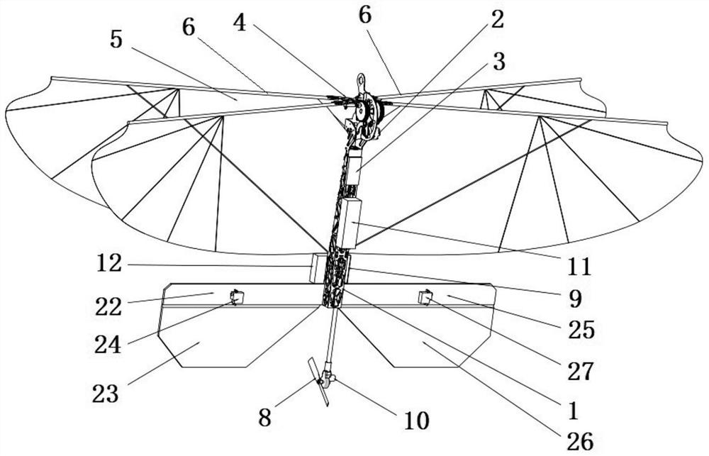
[0026] Such as Figures 1 to 3 As shown, a large-scale high-mobility hovering flapping-wing aircraft based on the clapping effect includes a fuselage 1 on which a flapping power system, a tail rotor bidirectional propulsion system, an energy source and a flight control system are installed;
[0027] The flapping power system is located at the front of the fuselage 1, and includes a driving motor 1, an electronic governor 3, a gear mechanism 4 and an X-shaped layout wing 5, and two spars 6 of the X-shaped layout wing 5 are arranged crosswise, and respectively It is rotatably and fixedly connected with the fuselage 1, and the two spars 6 are rotatably and fixedly connected with the gear mechanism 4 through a connecting rod 7 respectively. The body 1 swings, and the swing of the two spars 6 is a symmetrical linkage swing, so that the X-shaped layout wings 5 are symmetrically linked;
[0028] The drive motor one 2 is a brushless DC motor, and the rotation fixed points of the tw...
Embodiment 2
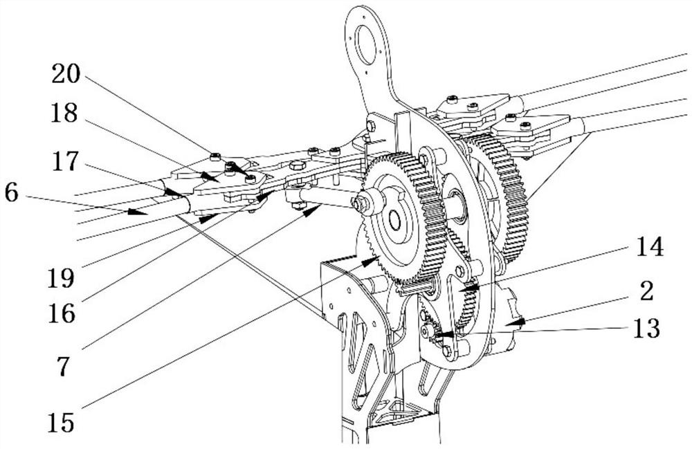
[0037] Such as figure 2 and 3 As shown, on the basis of Embodiment 1, the gear mechanism 4 includes a first-stage gear 13, a second-stage duplex gear 14 and two third-stage gears 15, each gear is installed vertically, and the drive motor one 2 is connected with the first-stage gear 13 , the primary gear 13 meshes with the secondary duplex gear 14, the secondary duplex gear 14 meshes with two tertiary gears 15, and the two connecting rods 7 are rotatably fixedly connected to a tertiary gear 15 respectively, and the connection points Eccentric position on the third stage gear 15.
[0038] The connection points corresponding to the two connecting rods 7 and the two third-stage gears 15 are left-right symmetrical; the drive motor 12 drives the first-stage gear 13 to rotate, the first-stage gear 13 drives the second-stage linkage gear to rotate, and the second-stage linkage gear drives two third-stage linkage gears to rotate. The gears 15 rotate at the same time, and the connect...
Embodiment 3
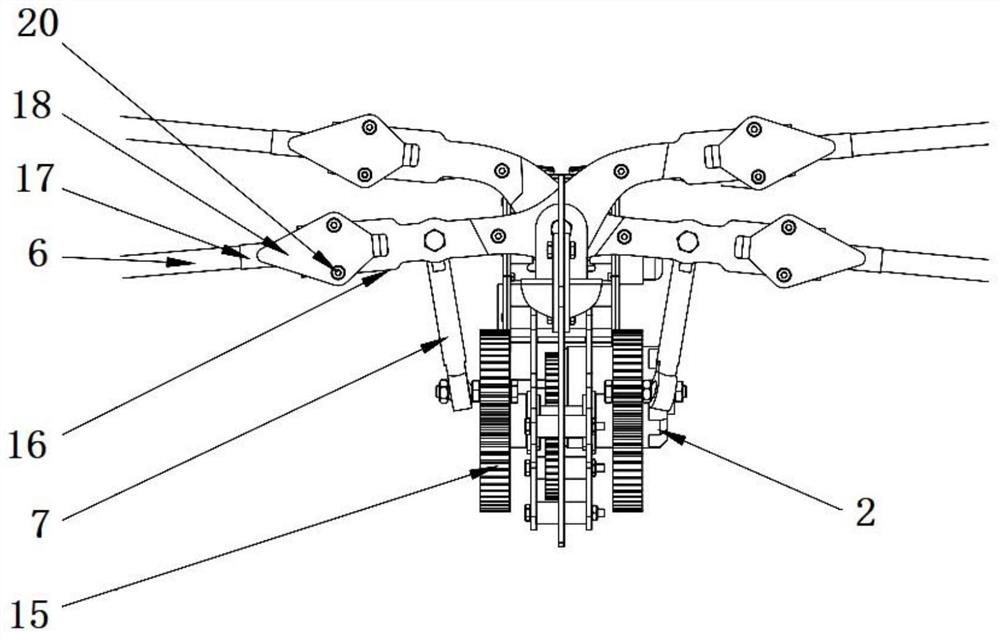
[0040] Such as Figures 2 to 4 As shown, on the basis of Embodiment 2, each spar 6 includes two sections on the left and right, and the left and right spar sections are detachably fixedly connected by a fork-shaped rocker 16, and the inner ends of the left and right spar sections are covered with elastic The rod cover 17 and the left and right ends of the bifurcated rocker 16 have openings, and the elastic rod sleeves 17 of the left and right spar sections are respectively located in the corresponding openings, and are pressed and fixed by the front pressing piece 18 and the rear pressing piece 19 , so that the left and right spar sections are fixedly connected to the middle fork-shaped rocker 16, specifically, the front pressing piece 18 and the rear pressing piece 19 are fixedly connected by bolts 20 and nuts 21, enabling quick disassembly and assembly.
[0041] The left and right spar sections and the openings at the left and right ends of the forked rocker 16 are fixedly c...
PUM
 Abstract
Description
Claims
Application Information
 - R&D
- Intellectual Property
- Life Sciences
- Materials
- Tech Scout
- Unparalleled Data Quality
- Higher Quality Content
- 60% Fewer Hallucinations
Browse by: Latest US Patents, China's latest patents, Technical Efficacy Thesaurus, Application Domain, Technology Topic, Popular Technical Reports.
© 2025 PatSnap. All rights reserved.Legal|Privacy policy|Modern Slavery Act Transparency Statement|Sitemap|About US| Contact US: help@patsnap.com


