High-transmittance microwave absorption light window with electrically controlled and adjustable reflection frequency band

A technology of electronic control adjustment and microwave absorption, applied in optics, electrical components, optical components, etc., can solve problems such as poor light transmittance, inability to adjust the frequency band of reflection, complex design and excitation control, etc.

Active Publication Date: 2021-02-05
HARBIN INST OF TECH
View PDF44 Cites 10 Cited by
  • Summary
  • Abstract
  • Description
  • Claims
  • Application Information

AI Technical Summary

Problems solved by technology

However, since the optical transmittance of the phase change material itself is only 30% in the metallic state, it is necessary to strictly control its relative area if it is to be applied to a transparent window.
However, in the above-mentioned patents, large-area phase-change materials are used to achieve adjustable filtering or absorption, and optical transparency is not considered, so they cannot be applied to light windows.
[0014] In summary, the existing transparent electromagnetic shielding technologies and frequency selective surfaces are difficult to simultaneously achieve high optical transparency, tunable reflection frequency band and absorption-based out-of-band suppression
Microwave absorption technology with optical transparency usually has a fixed operating frequency as the device is

Method used


Image

  • High-transmittance microwave absorption light window with electrically controlled and adjustable reflection frequency band
  • High-transmittance microwave absorption light window with electrically controlled and adjustable reflection frequency band
  • High-transmittance microwave absorption light window with electrically controlled and adjustable reflection frequency band

Examples


Embodiment 1

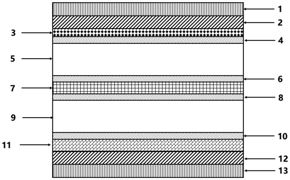
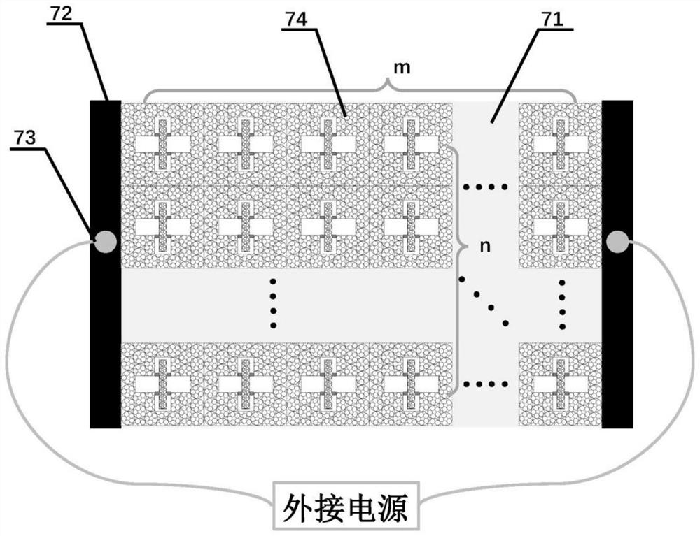
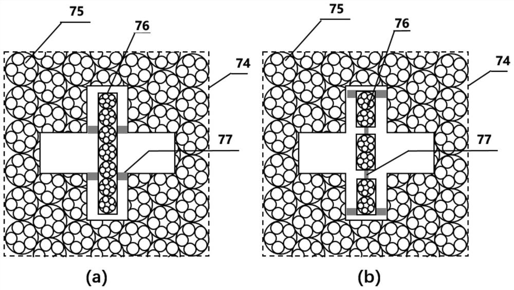
[0066] According to an embodiment of the present invention such as Figure 10 As shown, its overall structure diagram is shown in Figure 10 As shown in (a), the top layer consists of the first single-layer graphene layer, the second layer of transparent silica, the third layer of electrically controlled adjustable frequency selective surface layer integrated with phase change materials, the fourth layer of transparent silica, The fifth layer of metal mesh layer is composed of the structure diagram of the electronically controlled adjustable frequency selective surface layer integrated with phase change materials in the third layer as shown in Figure 10 (b) shown. In this example, the electronically controlled adjustable frequency selection surface layer and the metal grid layer of the integrated phase change material are used. The metal grids used are triangular distribution rings and sub-ring array grids; the stagger angle is 20°; the aperture type frequency selection Sur...

Embodiment 2

[0071] According to an embodiment of the present invention such as Figure 13 As shown, its overall structure diagram is shown in Figure 13 As shown in (a), the top layer consists of the first single-layer graphene layer, the second layer of transparent silica, the third layer of electrically controlled adjustable frequency selective surface layer integrated with phase change materials, the fourth layer of transparent silica, The fifth layer of metal mesh layer is composed of the structure diagram of the electronically controlled adjustable frequency selective surface layer integrated with phase change materials in the third layer as shown in Figure 13 (b) shown. In this embodiment, the electronically controlled adjustable frequency selection surface layer and the metal grid layer of the integrated phase change material are all made of triangular distribution rings and sub-ring array grids; the stagger angle is 20°; the aperture frequency Select the cross-aperture type fre...

Embodiment 3

[0076] According to an embodiment of the present invention such as Figure 16 As shown, its overall structure diagram is shown in Figure 16 As shown in (a), the top layer consists of the first single-layer graphene layer, the second layer of transparent silica, the third layer of electrically controlled adjustable frequency selective surface layer integrated with phase change materials, the fourth layer of transparent silica, The fifth layer of metal mesh layer is composed of the structure diagram of the electronically controlled adjustable frequency selective surface layer integrated with phase change materials in the third layer as shown in Figure 16 (b) shown. In this embodiment, the electronically controlled adjustable frequency selection surface layer and the metal grid layer of the integrated phase change material are all made of triangular distribution rings and sub-ring array grids; the stagger angle is 20°; the aperture frequency Select the cross-aperture type fre...


PUM

PropertyMeasurementUnit
Thicknessaaaaaaaaaa
Thicknessaaaaaaaaaa
Return lossaaaaaaaaaa

Abstract

The invention discloses a high-transmittance microwave absorption light window with an electrically controlled and adjustable reflection frequency band, and belongs to the field of optical transparentelectromagnetic shielding and microwave communication. The light window is formed by assembling a graphene layer, a transparent dielectric layer A, an electronic control adjustable frequency selective surface layer integrated with a phase change material, a transparent dielectric layer B and a metal mesh layer which are sequentially overlapped and arranged in parallel. The electronic control adjustable frequency selective surface layer of the integrated phase change material is composed of a frequency selective surface of the integrated phase change material, a metal electrode and a lead. Thefrequency selective surface of the integrated phase-change material is formed by periodically and closely connecting and arranging frequency selective surface array units of the integrated phase-change material, wherein the frequency selective surface array units are composed of a grid mesh aperture type frequency selective surface, a grid mesh patch type frequency selective surface and tiny phase-change material patches. The invention solves the problem that the existing microwave reflector is difficult to realize high optical transparency, adjustable reflection frequency band and out-of-band rejection of the reflection frequency band at the same time so as to mainly realize absorption.

Description

technical field [0001] The invention belongs to the fields of optically transparent electromagnetic shielding and microwave communication, and in particular relates to a high-transmittance microwave-absorbing light window whose reflection frequency band can be electrically controlled and adjusted. Background technique [0002] In recent years, electromagnetic waves have become more and more closely related to people's daily life. With the rapid development of radio, television, radar, satellite communication and navigation, wireless positioning technology, mobile communication / mobile phone, Internet of Things and other technologies, it has the function of transmitting and receiving electromagnetic waves. The number of devices has increased by orders of magnitude. The application band of electromagnetic waves continues to widen, and the intensity of electromagnetic waves continues to increase, making the space electromagnetic environment increasingly complex. While the wide ...

Claims


Application Information

Patent Timeline
IPC IPC(8): H01Q15/00H01Q17/00G02B5/00
CPCH01Q15/002H01Q15/0026H01Q17/00G02B5/00
Inventor 陆振刚张怡蕾谭久彬王赫岩
Owner HARBIN INST OF TECH
Why Eureka
Try Eureka