Catalytic combustion device for industrial waste gas treatment

A catalytic combustion and industrial waste gas technology, applied in the direction of combustion type, combustion method, clean heat transfer device, etc., can solve the problems of waste of resources, low purification efficiency, complex components, etc., and achieve long residence time, improved efficiency, and large contact area Effect

Inactive Publication Date: 2021-02-09
山东天智信息科技有限公司
View PDF17 Cites 0 Cited by
  • Summary
  • Abstract
  • Description
  • Claims
  • Application Information

AI Technical Summary

Problems solved by technology

[0002] Industrial waste gas refers to the general term for all kinds of pollutant gases discharged into the air generated during fuel combustion and production processes in the enterprise factory area. A large amount of industrial waste gas is produced in the production processes of chemical, steel, pharmaceutical, coking, oil refining and other industries , the composition of these exhaust gases is complex. If they are directly discharged into the atmosphere, they will have an irreversible impact on the environment and even threaten human health. The following problems occur during the use of existing industrial exhaust gas treatment catalytic combustion devices:
[0003] 1) During the combustion process, smoke and dust will be generated, which often accumulate in narrow air ducts and are difficult to clean;
[0004] 2) Waste heat is not utilized, and heating devices are often used to preheat the exhaust gas, and the waste heat generated by combustion is directly discharged, resulting in waste of resources;
[0005] 3) Direct catalytic combustion of industrial waste gas without dust removal and water removal treatment, resulting in insufficient combustion, low purification efficiency, and even secondary pollution

Method used


Image

  • Catalytic combustion device for industrial waste gas treatment
  • Catalytic combustion device for industrial waste gas treatment
  • Catalytic combustion device for industrial waste gas treatment

Examples


Embodiment Construction

[0023]To facilitate the understanding of those skilled in the art, the following is attachedFigure 1-7, The technical scheme of the present invention is further explained in detail.

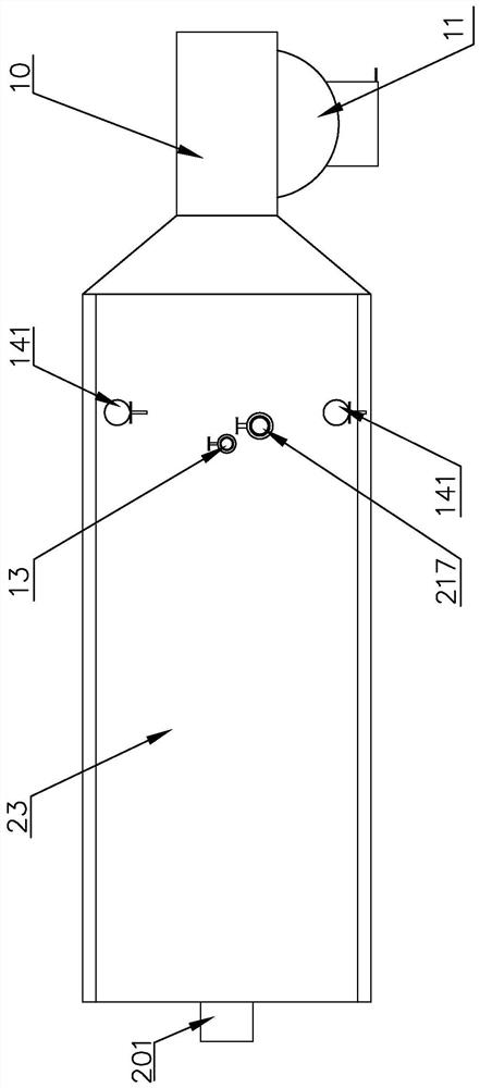
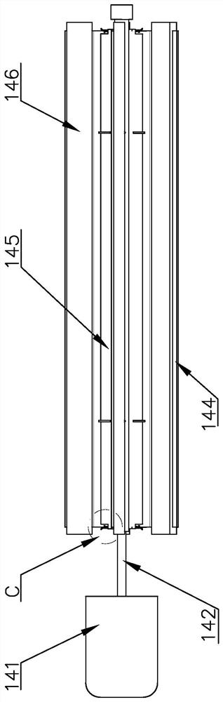
[0024]A catalytic combustion device for industrial waste gas treatment, including an air intake pipe 10, a dust removal device 11, a filter plate 12, a flow sharing mechanism 14, a heat exchange pipe 17, a baffle plate 16, a spoiler fan 18, a plate catalyst 19, and a combustion chamber 20 , Air duct 22, dust baffle 221, recoil air device 21, buffer chamber 15, air outlet pipe 13, the air inlet pipe 10 is arranged on the side of the box body 23, and the air inlet pipe 10 is provided with a dust removal device 11, the dust removal The device 11 includes a housing 117, a dust filter 112, a rotating shaft 116, a gear 115, a vent 111, a dust storage box 113, and a baffle 114. The two sides of the housing 117 are provided with vents 111, and a rotating shaft 116 is provided inside, and the rotating shaft 116 is...


PUM


Abstract

The invention discloses a catalytic combustion device for industrial waste gas treatment, which comprises a gas inlet pipe, a dust removal device, a filter plate, flow equalizing mechanisms, a heat exchange pipe, a flow guide plate, a turbulent flow fan, a plate type catalyst, a combustion chamber, an air duct, a dust baffle plate, a back flushing device, a buffer chamber and a gas outlet pipe; the air inlet pipe is arranged at one side of a box body; the dust removal device is arranged inside the air inlet pipe; the dust removal device comprises a shell, a dust filtering plate, a rotating shaft, shifting teeth, ventilation openings, a dust storage box and a baffle; the ventilation openings are arranged at the two sides of the shell; the rotating shaft is arranged in the shell and fixedlyconnected with the dust filtering plate; the dust storage box is arranged at the bottom of the shell and communicated with the shell; the shifting teeth are arranged between the dust storage box and the shell; the filter plate is arranged at an air outlet of the gas inlet pipe; and flow equalizing mechanisms are respectively arranged above and below one side of the filter plate. Waste gas can be fully degraded, waste heat utilization is achieved, and an internal air duct can be cleaned.

Description

Technical field[0001]The invention belongs to the technical field of waste gas treatment, and particularly relates to a catalytic combustion device for industrial waste gas treatment.Background technique[0002]Industrial waste gas refers to the general term of various pollutant-containing gases discharged into the air during the fuel combustion and production processes in the factory area. A large amount of industrial waste gas is generated during the production process of the chemical, steel, pharmaceutical, coking, and oil refining industries. , The components of these exhaust gases are complex. If they are directly discharged into the atmosphere, they will have an irreversible impact on the environment and even threaten human health. The existing industrial exhaust gas treatment catalytic combustion devices have the following problems during use:[0003]1) During the combustion process, smoke and dust will be generated, which are often accumulated in a narrow air duct and are diffic...

Claims


Application Information

Patent Timeline
Patent Type & Authority Applications(China)
IPC IPC(8): F23G7/07F23G5/44F23G5/46F23J3/02F23J15/02F28G1/16
CPCF23G7/07F23G7/068F23G5/46F23G5/44F23J3/02F23J15/025F28G1/163F23G2206/10F23J2217/10
Inventor 郑林
Owner 山东天智信息科技有限公司
Why Eureka
Try Eureka