Three-phase three-level rectifier based on three-winding isolation transformers
An isolation transformer and three-level rectification technology, which is applied in the direction of converting AC power input to DC power output, electrical components, output power conversion devices, etc., can solve problems such as complex control, achieve zero-crossing distortion, and reduce the number of diodes , The effect of loss reduction
- Summary
- Abstract
- Description
- Claims
- Application Information
AI Technical Summary
Problems solved by technology
Method used
Image
Examples
Embodiment 1
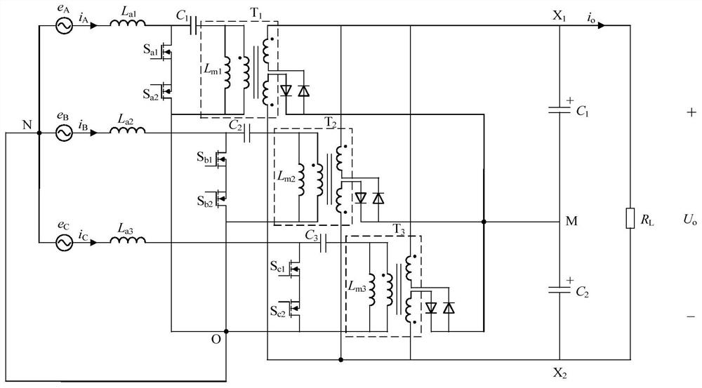
[0020] Embodiment 1: a three-phase three-level rectifier of a three-phase four-wire system, such as figure 1 shown, including three input filter inductors L a1 , L a2 , L a3 , three energy storage capacitors C 1 、C 2 、C 3 , Three three-winding isolation transformers T 1 , T 2 , T 3 , three sets of bidirectional switches (the first set of S a1 , S a2 ;Second group S b1 , S b2 ; The third group S c1 , S c2 ), six power diodes and two output filter capacitors C o1 、C o2 ;
[0021] Each phase of the input power supply is connected in series with an input filter inductor and a group of bidirectional switches in sequence, the ends of the three groups of bidirectional switches are connected together, the connection point is point O, and the neutral line of the three-phase input power supply is connected to point O;
[0022] Each energy storage capacitor is connected in series with the primary winding of a three-winding isolation transformer, and connected in parallel ...
Embodiment 2
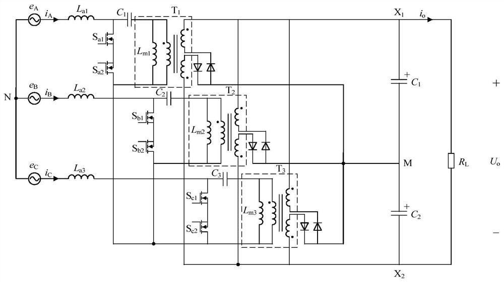
[0048] Embodiment 2: a three-phase three-level rectifier of a three-phase three-wire system, such as figure 2 shown, including three input filter inductors L a1 , L a2 , L a3 , three energy storage capacitors C 1 、C 2 、C 3 , Three three-winding isolation transformers T 1 , T 2 , T 3 , three sets of bidirectional switches (the first set of S a1 , S a2 ;Second group S b1 , S b2 ; The third group S c1 , S c2 ), six power diodes and two output filter capacitors C o1 、C o2 ;
[0049] Each phase of the input power supply is respectively connected in series with an input filter inductor and a group of bidirectional switches, and the ends of the three groups of bidirectional switches are connected together;
[0050] Each energy storage capacitor is connected in series with the primary winding of a three-winding isolation transformer, and connected in parallel with a group of bidirectional switches after being connected in series;
[0051] The secondary side of each t...
Embodiment 3
[0141]Embodiment 3: This embodiment is a circuit diagram of a three-phase three-level rectifier based on a three-winding isolation transformer based on an improved three-phase three-wire system based on embodiment 2, as shown in Figure 12 shown.
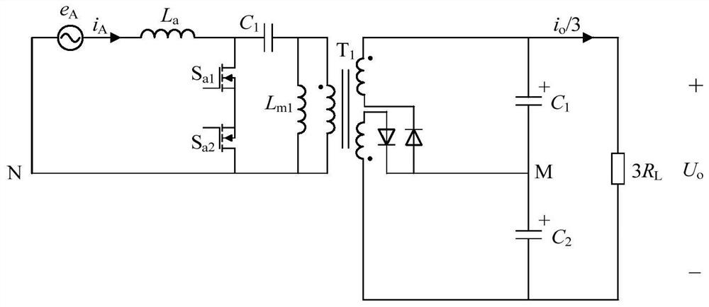
[0142] Taking the single-phase model as an example, such as Figure 13 As shown, the influence of the coupled inductance on the circuit will be analyzed in detail. Due to the three-phase power balance, for each phase, its load resistance is 3R L , that is, the output current is i o / 3. L a1 and L b1 The self-inductance of the coupled inductors are L 1 , L 2 , the mutual inductance is M(L 1 >M,L 2 >M). Considering that there is a freewheeling phase on the input side in each switching cycle, the energy storage capacitor voltage u C1 vs. input voltage e A equal, i.e. u C1 =e A . The extremely small excitation current of the transformer is ignored in the analysis.
[0143] bi-directional switch (S a1 , S a2 ) is turned...
PUM
 Abstract
Description
Claims
Application Information
 - R&D
- Intellectual Property
- Life Sciences
- Materials
- Tech Scout
- Unparalleled Data Quality
- Higher Quality Content
- 60% Fewer Hallucinations
Browse by: Latest US Patents, China's latest patents, Technical Efficacy Thesaurus, Application Domain, Technology Topic, Popular Technical Reports.
© 2025 PatSnap. All rights reserved.Legal|Privacy policy|Modern Slavery Act Transparency Statement|Sitemap|About US| Contact US: help@patsnap.com


