
Carbon tank electromagnetic valve and pipeline system for eliminating airflow pulsation and noise in vehicle

A technology for in-vehicle noise and airflow pulsation, which is applied in the charging system, the valve's device for absorbing fluid energy, and pipe components, which can solve the problems of reducing pipeline flow performance, high cost, and occupying space.

Active Publication Date: 2021-02-19
SAIC-GM-WULING AUTOMOBILE CO LTD
View PDF18 Cites 1 Cited by
  • Summary
  • Abstract
  • Description
  • Claims
  • Application Information

AI Technical Summary

Problems solved by technology

[0003]At present, the solution to the noise caused by the airflow pulsation in the pipeline is generally to install energy storage buffers, Helmholtz resonance boxes, expansion chambers, etc. on the pipeline, and the cost It is relatively high and needs to occupy a certain amount of space. It cannot be implemented under the condition that the space does not allow or can only adopt other methods, such as designing multiple similar devices with smaller sizes.
In addition, the expansion buffer elements connected in series in the pipeline also increase the local pressure loss and reduce the flow performance of the pipeline, which is not the optimal solution

Method used


Image

  • Carbon tank electromagnetic valve and pipeline system for eliminating airflow pulsation and noise in vehicle
  • Carbon tank electromagnetic valve and pipeline system for eliminating airflow pulsation and noise in vehicle
  • Carbon tank electromagnetic valve and pipeline system for eliminating airflow pulsation and noise in vehicle

Examples


Embodiment Construction

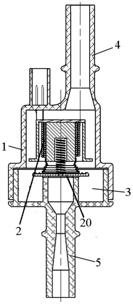
[0045] If there is a description of the direction (up, down, inside and outside) in the present invention, it is based on Figure 4 The structure shown in is a reference description, but the actual application direction of the present invention is not limited thereto. Wherein, the bushing 8 is inside, and the upstream pipeline 6 is outside; the upstream pipeline 6 is on the top, and the intake pipe 4 is on the bottom.

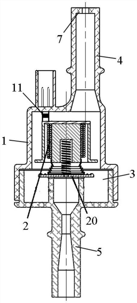
[0046] Combine below Figure 3 to Figure 19 , a carbon canister solenoid valve and pipeline system for eliminating airflow pulsation and interior noise of the present invention will be further described in detail.

[0047] A carbon canister solenoid valve and pipeline system that eliminates airflow pulsation and noise in the car according to the present invention, please refer to Figure 3 to Figure 17 , comprising a solenoid valve, an upstream pipeline 6 and a downstream pipeline, the solenoid valve comprises a valve body 1 and an inductance coil 2 arranged ...


PUM


Abstract

The invention discloses a carbon tank electromagnetic valve and pipeline system for eliminating airflow pulsation and noise in a vehicle. The carbon tank electromagnetic valve and pipeline system comprises an electromagnetic valve, an upstream pipeline and a downstream pipeline, wherein the electromagnetic valve comprises a valve body and an inductance coil, a valve cavity is formed in the valve body, a valve is arranged in the valve cavity, and an air inlet pipe and an air outlet pipe are arranged at the top and the bottom of the valve body respectively. The air inlet pipe communicates with the air outlet pipe through a valve in an opening and closing mode, the air inlet pipe communicates with a carbon tank through an upstream pipeline, a reducing portion with a through hole is arranged in the air inlet pipe or an upstream pipeline, and the radial sectional area of the through hole of the reducing portion is smaller than that of the air inlet pipe. Two ends of the inductance coil areelectrically connected with a positive electrode of an automobile storage battery and a PWM power amplification driving signal output end of an engine controller respectively, and a rectifier diode isreversely connected to the two ends of the inductance coil in parallel. According to the carbon tank electromagnetic valve and pipeline system for eliminating airflow pulsation and noise in the vehicle, the airflow pulsation and the noise in the vehicle, caused by the airflow pulsation can be reduced, the flow performance can be guaranteed, and the structure is simple.

Description

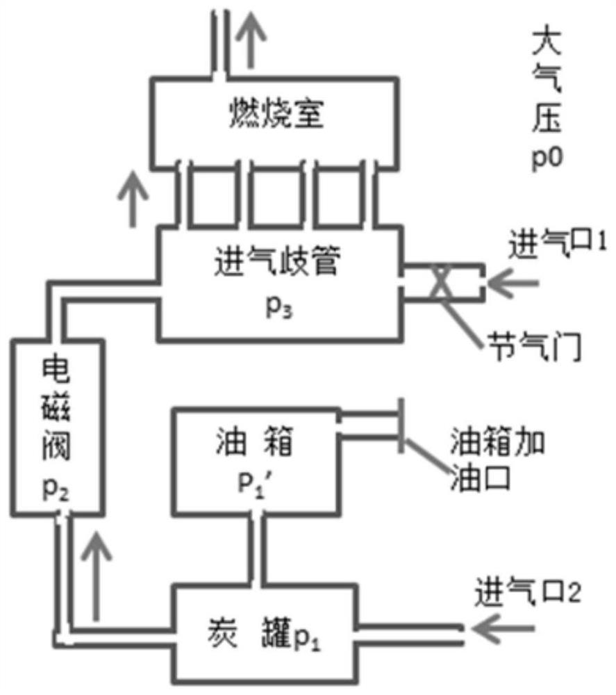
technical field [0001] The invention relates to a carbon canister solenoid valve, in particular to a carbon canister solenoid valve and a pipeline system for eliminating airflow pulsation and noise inside a car. Background technique [0002] With the promotion and implementation of the National VI emission policy, the requirements for vehicle fuel evaporative emissions have been further increased. In order to reduce emissions and meet the requirements of the national environmental protection policy, the vapor recovery flow rate of the fuel evaporation recovery system of the National VI vehicles is about double that of the National V vehicles. , you will hear the sound of the system running in the car when working under idling conditions. Automobile fuel evaporation recovery valve pipe capacity system such as figure 1 As shown in , a vapor recovery flow control valve (hereinafter referred to as solenoid valve) widely used in automotive fuel vapor recovery systems is a duty c...

Claims


Application Information

Patent Timeline
Patent Type & Authority Applications(China)
IPC IPC(8): F16K47/02F16K27/02F16K31/06F16L55/027F02M25/08
CPCF16K47/02F16K31/0655F16K31/0675F16K27/029F16L55/027F02M25/0836F02M25/0872
Inventor 田绍军王玉雷唐基荣黄金旺袁观练
Owner SAIC-GM-WULING AUTOMOBILE CO LTD
Learn More