
Urban rail train positioning and speed measurement method based on machine vision

An urban rail train and machine vision technology, applied in the field of rail transit, can solve the problems of accumulated errors, difficult maintenance and maintenance, large measurement errors, etc.

Pending Publication Date: 2021-02-19
CRRC NANJING PUZHEN CO LTD
View PDF0 Cites 8 Cited by
  • Summary
  • Abstract
  • Description
  • Claims
  • Application Information

AI Technical Summary

Problems solved by technology

There are obvious defects in the speed measurement of the wheel speed method: [1] When the wheelset idling, creeping, and slipping (such as braking) occur during the train operation, large measurement errors will occur; [2] wear will change the geometric size of the wheelset , Measuring the train mileage based on the geometric dimensions of the wheel set will produce a large measurement error; [3] The angle of rotation of the wheel set is too small, resulting in the inability to generate pulses and resulting in cumulative errors
This method is based on independent speed measurement equipment and does not involve the movement and wear of the wheel set, but it also has obvious disadvantages: [1] Doppler speed measurement has high environmental requirements, and the environment is not flat enough to cause radio waves to scatter, resulting in large measurement errors ;【2】Usually the Doppler speedometer is installed with a top view, and the measurement error caused by the installation angle needs to be corrected; The Doppler speedometer has a large error when driving
There are also obvious defects in the train positioning method based on querying transponders: [1] it can only locate at one point, and cannot realize real-time and continuous positioning; [2] the cost of densely deploying transponders along the track line is too high, and when the transponders are located Difficult to care and maintain
However, it is easily affected by the natural environment. Trains running in mountainous areas or tunnels have positioning blind spots. The current positioning accuracy cannot distinguish double-track tracks.

Method used


Image

  • Urban rail train positioning and speed measurement method based on machine vision
  • Urban rail train positioning and speed measurement method based on machine vision
  • Urban rail train positioning and speed measurement method based on machine vision

Examples


Embodiment Construction

[0051] The drawings constituting a part of the present invention are used to provide a further understanding of the present invention, and the schematic embodiments and descriptions of the present invention are used to explain the present invention, and do not constitute an improper limitation of the present invention.

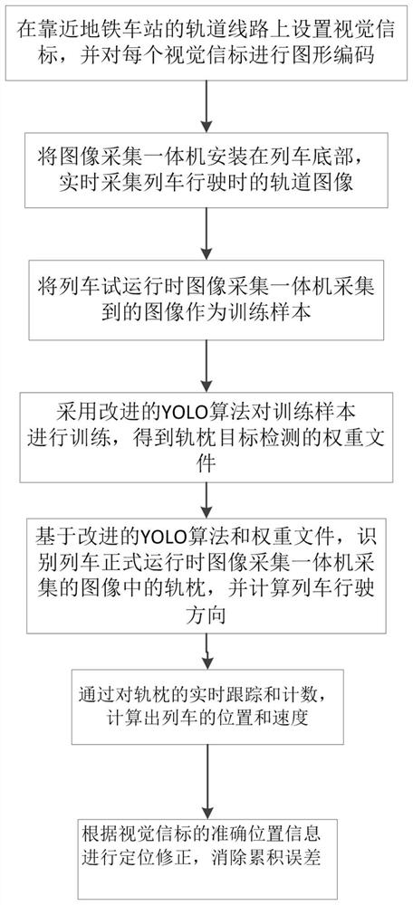
[0052] Such as figure 1 As shown, this embodiment provides a machine vision-based urban rail train positioning and speed measurement method. The track line is photographed by a high frame rate industrial camera and the visual beacon is set at a fixed point, and the improved YOLO algorithm is used to process the image in real time to obtain a sleeper. Counting to realize the positioning and speed measurement of urban rail trains. Specifically:

[0053] Step 1: Set up visual beacons on the track lines close to the subway station, and carry out graphic coding for each visual beacon, each graphic coding includes the exact position information of the corresponding...


PUM


Abstract

The invention discloses an urban rail train positioning and speed measurement method based on machine vision, and the method comprises the steps of photographing a rail line and a fixed-point set visual beacon through a high-frame-frequency industrial camera, carrying out the real-time processing of an image through an improved YOLO algorithm, obtaining the sleeper counting, and achieving the positioning and speed measurement of an urban rail train. Real-time processing of shot high-frame-frequency images is achieved, position information and speed information of a train are continuously tracked, the positioning precision is smaller than 0.1 m, the speed measurement precision reaches 0.1 km / h, and sleeper counting, positioning and speed measurement can be achieved when the urban rail trainruns at the speed of 120 km / h.

Description

technical field [0001] The invention belongs to the field of rail transit. Background technique [0002] In recent years, my country has continuously increased its investment in railway passenger dedicated lines and urban rail transit, and the status of rail transit has been increasing. The location information of rail vehicles is the basic data of rail transit vehicles running, testing and maintenance, and its research is becoming more and more important. With the rise of artificial intelligence technology, the application of new technologies such as machine vision, fault detection and diagnosis, and unmanned driving in the rail transit industry has flourished. In order to ensure the safe operation of trains and better serve the work of vehicle marshalling, dispatching, testing, and maintenance, it is of great theoretical and practical significance to study a vehicle-mounted high-precision, real-time, continuous, and independent positioning equipment. [0003] The basic f...

Claims


Application Information

Patent Timeline
Patent Type & Authority Applications(China)
IPC IPC(8): G06K9/00G06K9/62G06N3/04G06N3/08G06T7/73H04N5/225
CPCG06N3/08G06T7/73G06T2207/20081G06T2207/20084G06V20/588G06V2201/07H04N23/51G06N3/045G06F18/214
Inventor 黄涛吕红强张军贤王维周杨单奇宋兴国饶鑫蔡正凯
Owner CRRC NANJING PUZHEN CO LTD
Learn More