Semi-automatic assembling process for electronic components for electric appliances

A technology of electronic components and assembly process, which is applied in the field of semi-automatic assembly process of electronic components for electrical appliances. It can solve the problems of inability to quickly assemble spot welding, cumbersome clamping, and inapplicability to mass production, and achieve small horizontal space occupation and high degree of automation. , the effect of saving the workshop

Inactive Publication Date: 2021-02-26
HUZHOU TEACHERS COLLEGE
View PDF1 Cites 1 Cited by
  • Summary
  • Abstract
  • Description
  • Claims
  • Application Information

AI Technical Summary

Problems solved by technology

[0005] The purpose of the present invention is to address the deficiencies of the prior art, by setting the static contact top-mounting work to cooperate with the coil and the static contact welding to work together, to realize the automatic and precise welding of the static contact and the coil, and then to use the static contact top-mounting work The transmission makes it cooperate with the semi-finished product and the wiring board welding work, completes the automatic and precise welding work of the wiring board and the coil, makes the coil assembly automatic assembly, and uses the continuous transmission of the static contact to complete the automatic output of the assembled coil assembly work, thereby solving the technical problems that the coil, contact plate and static contact need to be positioned at the same time, the clamping is cumbersome, and the spot welding cannot be quickly assembled and is not suitable for mass production.

Method used


Image

  • Semi-automatic assembling process for electronic components for electric appliances
  • Semi-automatic assembling process for electronic components for electric appliances
  • Semi-automatic assembling process for electronic components for electric appliances

Examples


Embodiment 1

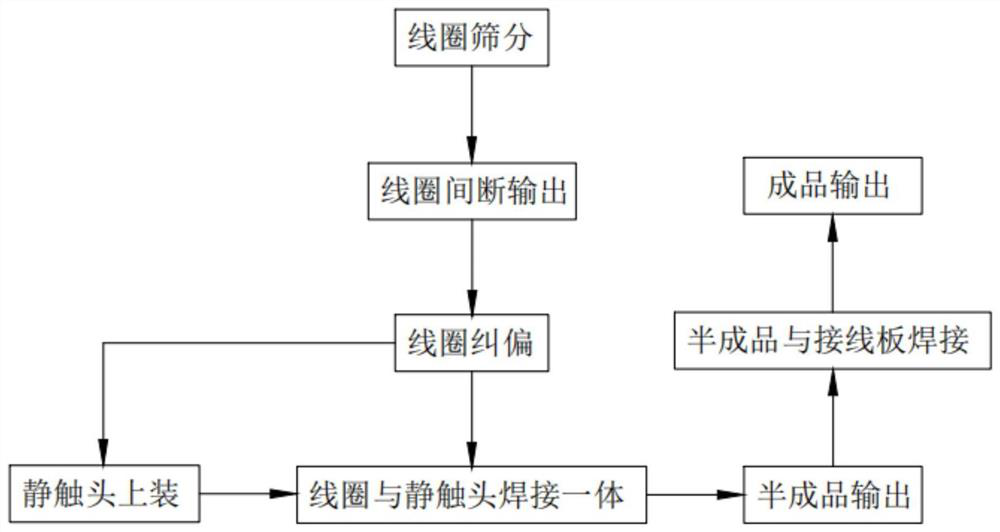
[0088] Such as figure 1 As shown, a semi-automatic assembly process of electronic components for electrical appliances, including:

[0089] Step 1, coil screening, start the first transmission assembly 12, the coil 10 randomly falls between the screw 121 and the optical axis 122, the rotating screw 121 cooperates with the optical axis 122 to drive the coil 10 to automatically lie flat, and faces the height limit mechanism 2-way transmission;

[0090] Step 2, the coil output intermittently, start the second transmission assembly 31, the partition 324 of the spacer assembly 32 is lifted between the corresponding first transmission assembly 12 under the guidance of the first guide assembly 33, and at the same time, the top plate 342 is transferred to the disc When it is directly below 341, the top plate 342 contacts the disc 341 and lifts it up, and a coil 10 smoothly passes through the roller shaft 21 of the height limiting mechanism 2 and outputs backward;

[0091] Step 3, th...

Embodiment 2

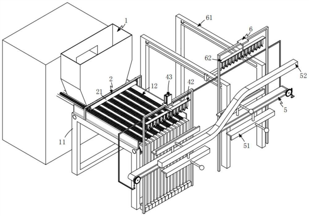
[0108] Such as figure 2 As shown, a semi-automatic assembly equipment for electronic components for electrical appliances, including:

[0109] The laying mechanism 1 includes a frame 11 and several groups of first transmission components 12 that are rotatably arranged on the frame 11 and extend along the length direction of the frame 11. The first transmission components 12. The synchronous transmission is driven by the first driving mechanism 13;

[0110] A height limiting mechanism 2, the height limiting mechanism 2 is installed on the frame 11 and arranged along the width direction of the frame 11, and the roller shaft 21 of the height limiting mechanism 2 is driven to rotate by a third drive mechanism 22;

[0111] The deviation correction mechanism 3, the deviation correction mechanism 3 is arranged below the first transmission assembly 12, which includes a second transmission assembly that is driven along the length direction of the frame 11 and arranged in several grou...

Embodiment 3

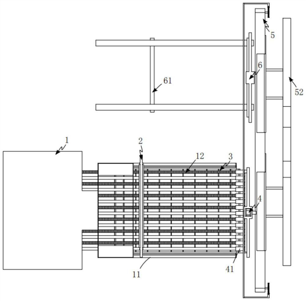
[0162] Such as Image 6 As shown, the parts that are the same as or corresponding to those in the second embodiment are marked with the corresponding reference numerals in the second embodiment. For the sake of simplicity, only the differences from the second embodiment will be described below. The difference between this embodiment three and embodiment two is:

[0163] Such as Image 6 As shown, the fourth transmission assembly 62 includes a connecting rod 621 that is fixedly connected to the connecting frame 434 at one end and is provided in a multi-stage structure, a second welding head group 622 installed on the connecting rod 621 and several fixed joints. The second hoop member 623 arranged below the connecting rod 621, the second hoop member 623 includes a telescopic unit e624 arranged vertically downward and a second semicircular hoop 625 arranged at the lower end of the telescopic unit e624 .

[0164] In this embodiment, by setting the fourth transmission assembly 6...


PUM


Abstract

The invention relates to a semi-automatic assembling process for electronic components for electric appliances. The semi-automatic assembling process for the electronic components for the electric appliances comprises the following steps of 1, screening coils; 2, intermittently outputting the coils; 3, correcting the deviations of the coils; 4, welding the coils and the static contacts into a whole; 5, loading the static contacts, wherein the static contacts are manually placed on a static contact positioning tool at the input end of a chain wheel and chain transmission unit b in sequence, a first one-way rack vertically moves downwards while a linear air cylinder is started, a first driving gear is driven to rotate, the first driving gear drives the chain wheel and chain transmission unitb to transmit, and the chain wheel and chain transmission unit b drives the static contact positioning tool to be transmitted to the position under a first welding head set and waits for completing welding work; 6, outputting semi-finished products; 7, welding the semi-finished products and wiring boards; and 8, outputting finished products. According to the semi-automatic assembling process forthe electronic components for the electric appliances provided by the invention, the technical problems that the coils, contact plates and the static contacts need to be positioned at the same time, clamping is tedious, assembling and spot welding cannot be rapidly conducted, and an existing process is not suitable for batch production are solved.

Description

technical field [0001] The invention relates to the technical field of electronic components, in particular to a semi-automatic assembly process of electronic components for electrical appliances. Background technique [0002] The coil assembly in the miniature circuit breaker is a key part of the electromagnetic tripping structure. It consists of three parts: coil, static contact and wiring board; the wiring board is a strip-shaped plate structure, one end of the static contact is a hook that turns inward to form a hook, and the other end of the static contact is a strip-shaped The plate-shaped sheet part, the middle of the static contact is a fin, and the coil is extended with welding sheets at both ends. The welding sheet at one end of the coil is stacked on one end of the terminal board to form welding, and the welding sheet at the other end of the coil is stacked on the static contact fin. Welding is formed on the top, and the automatic welding machine for the coil ass...

Claims


Application Information

Patent Timeline
Patent Type & Authority Applications(China)
IPC IPC(8): B23K37/04B23K37/02B23K37/00B23K101/36
CPCB23K37/00B23K37/0247B23K37/0426B23K37/0461B23K2101/36
Inventor 张起祥
Owner HUZHOU TEACHERS COLLEGE
Why Eureka
Try Eureka