Fixing device and heat pump equipment

A technology of fixing devices and heat pumps, applied in lighting and heating equipment, measuring devices, mechanical equipment, etc., can solve the problems of low assembly efficiency, increased operation difficulty, inconvenient installation, etc., achieve fast assembly, improve operation accuracy, and simple structure Effect

Pending Publication Date: 2021-02-26
QINGDAO HAIER NEW ENERGY ELECTRIC APPLIANCE +2
View PDF0 Cites 0 Cited by
  • Summary
  • Abstract
  • Description
  • Claims
  • Application Information

AI Technical Summary

Problems solved by technology

However, it is easy to have false welding or welding deviation when welding the temperature sensing sleeve, resulting in deviation of the test temperature
The different positions of the circlips will also lead to different positions of the temperature-sensing probe attached to the inner wall of the temperature-sensing sleeve, which will also cause deviations in the test temperature and reduce the accuracy of the unit’s operation.
In addition, welding consumes high energy, and the temperature-sensing sleeve is easily deformed during transportation, which affects the assembly efficiency of the temperature-sensing package
Moreover, a variety of materials need to be used in the final assembly process, and the assembly efficiency is low
[0004] Some of the existing fixing devices of the temperature-sensing package are provided with two arches, and a bayonet is provided on the opening side to form a ring-shaped fixing card. However, this assembly method requires the temperature-sensing package and the pipeline to be put together first, and then the temperature-sensing package, which increases the difficulty of operation
Moreover, the shape of the fixing card needs to be adjusted during use, which will cause imperfect fit between the fixing card and the pipeline.

Method used


Image

  • Fixing device and heat pump equipment
  • Fixing device and heat pump equipment
  • Fixing device and heat pump equipment

Examples


Embodiment 1

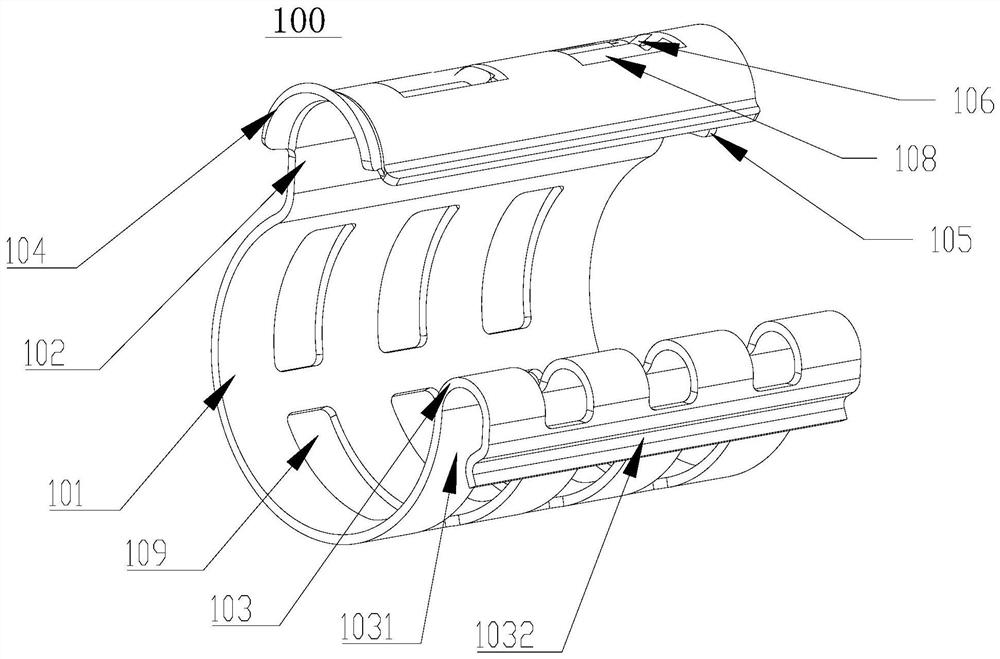
[0039] refer to Figure 1-5 As shown, the present invention discloses a fixing device 100. The fixing device 100 includes a first open sleeve 101 and a second open sleeve 102. The first open sleeve 101 is provided with a first opening 1011 in the axial direction, and the second opening The sleeve 102 is provided with a second opening 1021 in the axial direction; the first opening 1011 is disposed toward the second opening 1021, the first side of the first opening 1011 is connected to the first side of the second opening 1021, and the first side of the first opening 1011 is The two sides and the second side of the second opening 1021 are not connected, as the free side, forming the installation port 107 of the fixing device 100; the cylinder corresponding to the first opening sleeve 101 is outside the cylinder corresponding to the second opening sleeve 102 cut.

[0040] By setting the first open sleeve and the second open sleeve outwardly, the components installed in the two o...

Embodiment 2

[0050] This embodiment is a further optimization or limitation of Embodiment 1 or an equivalent replacement.

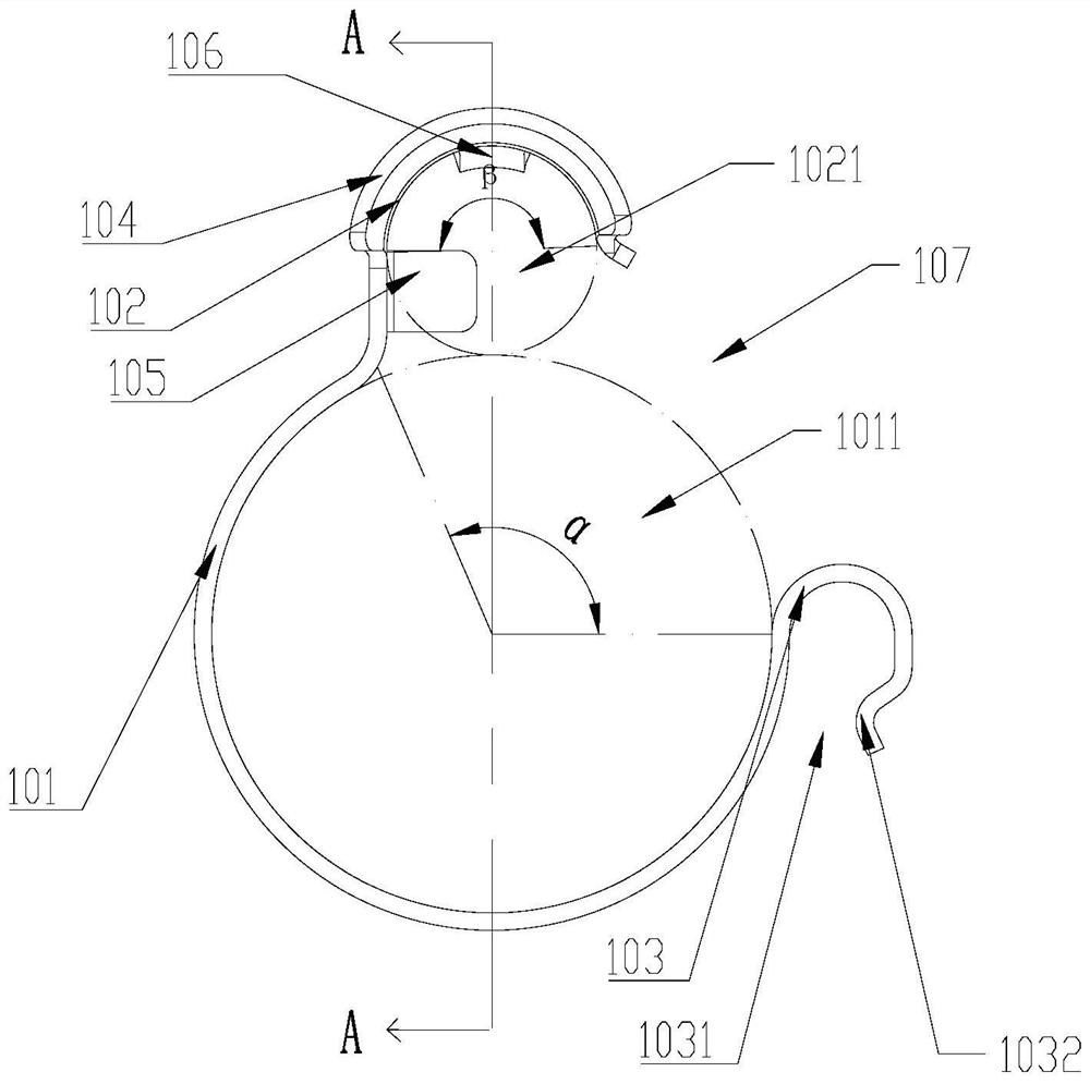
[0051] A fixing device 100, the fixing device 100 includes a first open sleeve 101, a second open sleeve 102, the first open sleeve 101, the second open sleeve 102 are provided with a first opening 1011, a second Two openings 1021; the first opening 1011 is opposite to the second opening 1021, the first side of the first opening 1011 is connected to the first side of the second opening 1021, the second side of the first opening 1011 and the second opening 1021 The second side is the free side, forming the installation port 107 of the fixing device 100; the corresponding cylinder of the first open sleeve 101 is circumscribed with the corresponding cylinder of the second open sleeve 102, and the radius of the first open sleeve 101 is greater than The radius of the second open sleeve 102 .

[0052] refer to figure 1 and figure 2 , wherein, the radian of the first ope...

Embodiment 3

[0060] This embodiment is a further optimization or limitation of embodiment 1 or embodiment 2 or an equivalent replacement.

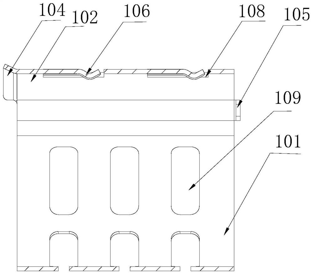
[0061] refer to figure 1 , image 3 and Figure 4 , the peripheral wall of the second open sleeve 102 is provided with a number of positioning holes 108, the elastic piece 106 is arranged in the positioning hole 108, the elastic piece 106 is inserted into the positioning hole 108, and the temperature sensing probe 300 is further compressed to make the temperature sensing The probe 300 fits closely with the temperature tube body 200 to be measured, so that the temperature measurement is more accurate.

[0062] Several hollow structures 109 are arranged on the peripheral wall of the first open sleeve 101, and the hollow structures 109 extend along the circumferential direction of the first open sleeve 101, so that the rigidity of the first open sleeve 101 is moderate, and the clamping installation is labor-saving convenient.

[0063] refer to figur...


PUM


Abstract

The invention belongs to the technical field of electrical equipment, and particularly relates to a fixing device which comprises a first opening sleeve provided with a first opening in the axial direction and a second opening sleeve provided with a second opening in the axial direction. The first opening faces the second opening, and a first side of the first opening is connected with a first side of the second opening. A second side of the first opening and a second side of the second opening are free sides and form a mounting opening of the fixing device. A cylinder corresponding to the first opening sleeve is externally tangent to a cylinder corresponding to the second opening sleeve. The fixing device is simple in structure, and one structure can be tightly fixed to the outer side ofthe other structure conveniently without welding. The invention further relates to heat pump equipment of which a temperature sensing probe is installed through the fixing device.

Description

technical field [0001] The invention belongs to the technical field of electrical equipment, and in particular relates to a fixing device and heat pump equipment. Background technique [0002] In the air conditioning system, when the outdoor working conditions are severe, the system pressure will be abnormally high. At this time, the exhaust temperature is much higher than that under normal outdoor working conditions, and the cylinder temperature of the compressor will also exceed the safe range, resulting in frequent start and stop of the compressor. . In order to ensure the safe operation of the air conditioning system, it is necessary to measure the temperature of the refrigerant through the temperature sensor to adjust the operating state of the air conditioner. [0003] In the prior art, the temperature-sensing probe is fixed by the copper tube of the probe. First, the copper temperature-sensitive sleeve is welded to the surface of the temperature-measuring pipe. The p...

Claims


Application Information

Patent Timeline
Patent Type & Authority Applications(China)
IPC IPC(8): G01K1/14F24F11/89F24H9/20
CPCF24H9/2007F24F11/89G01K1/14
Inventor 杨磊李建民魏爱国康乐刘玉君管祥华高家富侯梅梅李羲龙
Owner QINGDAO HAIER NEW ENERGY ELECTRIC APPLIANCE
Why Eureka
Try Eureka