Method for reducing wire length, electronic equipment and computer readable storage medium

A computer program and line length technology, which is applied in the field of EDA tools for integrated circuit layout design, can solve problems such as large influence of physical wiring, and achieve the effect of reducing line length

Active Publication Date: 2021-02-26
北京华大九天科技股份有限公司
View PDF7 Cites 0 Cited by
  • Summary
  • Abstract
  • Description
  • Claims
  • Application Information

AI Technical Summary

Problems solved by technology

In advanced technology, the impact of physical wiring is getting bigger and bigger, and the impact of wiring delay even exceeds the delay of the unit itself.

Method used


Image

  • Method for reducing wire length, electronic equipment and computer readable storage medium
  • Method for reducing wire length, electronic equipment and computer readable storage medium
  • Method for reducing wire length, electronic equipment and computer readable storage medium

Examples


Embodiment 1

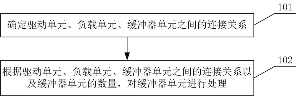
[0029] figure 1 For the method flowchart according to the reduction line length of the present invention, below will refer to figure 1 , the method for reducing the wire length of the present invention is described in detail.

[0030] First, in step 101, the connection relationship among the driving unit, the load unit and the buffer unit is determined.

[0031] In the embodiment of the present invention, after the rationalized layout engine determines the placement position of the buffer unit (Buffer), it is necessary to determine whether the position of the Buffer unit is within the span range of the drive unit (Source unit) and the load unit (Sink) in the x direction. unit) range.

[0032] In step 102, the buffer units are processed according to the connection relationship among the drive unit, the load unit, and the buffer units and the number of the buffer units.

[0033] In the embodiment of the present invention, if the position of the Buffer unit is within the range...

Embodiment 2

[0043] In the embodiment of the present invention, it is assumed that a certain line network in the circuit: Source is a driving unit, and Sink is a load unit. In order to optimize the timing target from Source to Sink, three buffer units are inserted in the middle, and the target positions of the three buffer units on the chip unit row have been obtained.

[0044] The first step is to determine the connection relationship between the drive unit, load unit and buffer unit as follows:

[0045] Source->Buffer3->Buffer2->Buffer1->Sink.

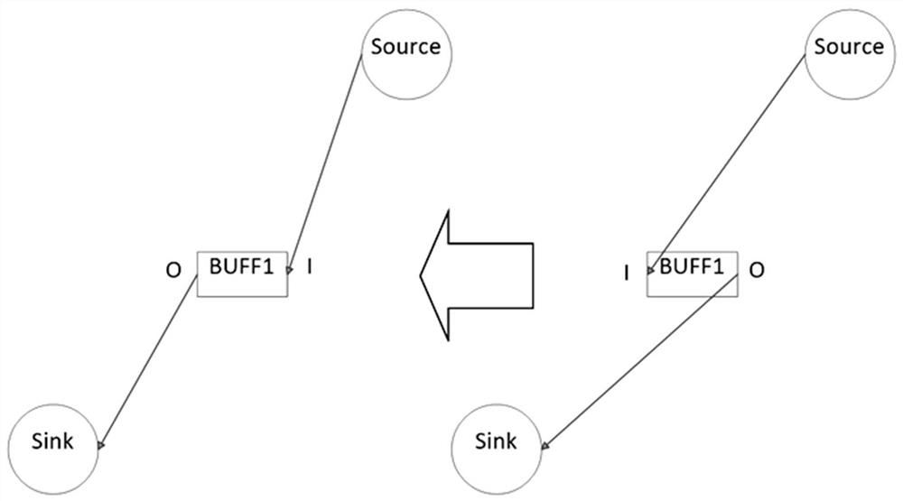
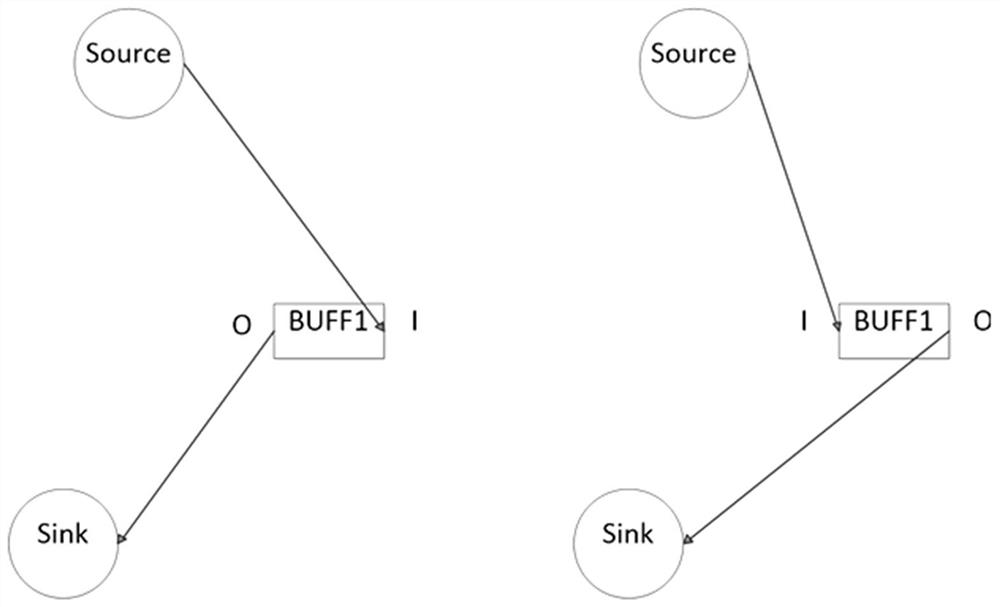
[0046] In the second step, the buffer unit Buffer1 is processed. Check if the output O pin of Buffer1 is closer to the sink unit than the input I pin. If not, perform a horizontal unit flip on the buffer unit Buffer1 so that the O pin is closer to the Sink unit.

[0047] The third step is to process the buffer unit Buffer2. Check that the output O pin of Buffer2 is closer to the Buffer1 cell than the input I pin. If not, perform a horizontal...


PUM


Abstract

The invention discloses a method for reducing the wire length, which is characterized by comprising the steps of determining a connection relationship among a driving unit, a load unit and a buffer unit; and overturning and adjusting the buffer unit according to the position of the buffer unit. According to the method for reducing the wire length, when the buffer unit is inserted, the purposes ofreducing the wiring length and reducing the wiring difficulty are achieved by turning over the buffer unit and changing the positions of the unit pins according to the positions of the units in the chip and the actual condition of physical wiring, so that the influence of a timing sequence ECO optimization scheme on local wiring is smaller, and the accuracy and the consistency are better.

Description

technical field [0001] The invention relates to the technical field of EDA (Electronics Design Automation, electronic design automation) tools for layout design of integrated circuits, in particular to a wiring method for EDA tools in layout design of integrated circuits. Background technique [0002] In digital integrated circuit design, in order to ensure that the chip can work normally and achieve the expected frequency, it is necessary to check whether the time when the clock signal and data signal arrive at the register synchronization unit meets the constraints of setup time and hold time. If timing violations are found, ECO modifications are required to adjust the timing paths. [0003] Because buffer cells do not change the logic function of the circuit, buffer cell insertion has become the most commonly used optimization method in timing optimization. For example, when fixing the timing violation of the Hold hold time, a buffer unit may be inserted on the timing pa...

Claims


Application Information

Patent Timeline
Patent Type & Authority Applications(China)
IPC IPC(8): G06F30/394
CPCG06F30/394
Inventor 周汉斌刘毅陈彬董森华
Owner 北京华大九天科技股份有限公司
Why Eureka
Try Eureka