Rapid inflating and deflating device for celebration palace lantern

A technology of inflating and deflating, palace lanterns, applied in the installation device of container structure, container filling method, fixed-capacity gas storage tank, etc., can solve the problems of not emphasizing work efficiency, increasing material cost, and consuming physical strength, so as to improve repeated use. efficiency, reduced material costs, and the effect of convenient operation

Active Publication Date: 2021-03-02
BEIJING RES INST OF SPATIAL MECHANICAL & ELECTRICAL TECH
View PDF13 Cites 1 Cited by
  • Summary
  • Abstract
  • Description
  • Claims
  • Application Information

AI Technical Summary

Problems solved by technology

[0005]1. Since the same flexible film interface is used to inflate and deflate, it is necessary to hold the flexible film interface tightly to cover the air source inflation tube and pressure sensor when inflating. Due to the long inflation time, the actual operation is more labor-intensive and prone to air leakage;
[0006]2. On the premise of not emphasizing the work efficiency, the inflatable tube can be used to discharge helium, but because the diameter of the deflated tube is relatively small, the discharge efficiency is relatively low. Seriously affect the retractable efficiency of the celebration palace lanterns;
[0007]3. In order to ensure the rapid discharge of helium in the celebration palace lanterns, it is necessary to completely cut the film of the inflatable tube from the vent tube to increase the area of ​​the discharge port to improve Emission efficiency; but it is followed by an increase in material costs. Due to the destruction of the inflation and deflation film structure, a new inflation and deflation structure needs to be used when re-testing, resulting in an increase in material costs

Method used


Image

  • Rapid inflating and deflating device for celebration palace lantern
  • Rapid inflating and deflating device for celebration palace lantern
  • Rapid inflating and deflating device for celebration palace lantern

Examples


Embodiment Construction

[0027] The present invention will be further elaborated below in conjunction with embodiment.

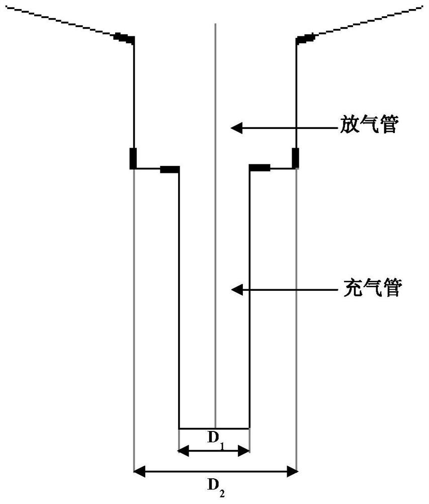
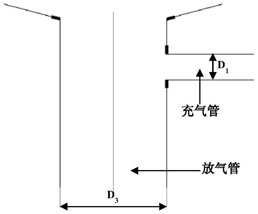
[0028] Such as image 3 As shown, firstly, the overall diameter of the flexible film interface is enlarged to D 3 , remove the part of the inflation tube from the interface of the flexible film, and change the diameter of the deflation tube by D 2 increase to D 3 , and at the same time branch out the diameter D on the vent pipe 1 The inflatable tube realizes the separation design of the inflatable and deflated ports. Before inflating, tighten the deflation tube with a larger diameter and use the inflation tube to inflate to facilitate operation; when deflation, open the air port to ensure rapid exhaust.

[0029] The diameter of the vent pipe D 3 After a lot of theoretical analysis and verification, the radius R of the celebration palace lantern and the longest deflation working time T 1 , deflation velocity V 1 , the internal and external pressure difference ΔP of the air rel...


PUM


Abstract

The invention relates to a rapid inflating and deflating device for a celebration palace lantern. The rapid inflating and deflating device comprises an air bottle, an inflating valve and an inflatingtool, a flexible thin film connector of a celebration palace lantern inner container serves as a deflating pipe, an inflating pipe with the diameter smaller than that of the deflating pipe is branchedfrom the side of the deflating pipe, one end of the inflating tool is connected with the inflating pipe, the other end is connected with the inflating valve through a pipeline, the air bottle is connected with the inflating valve, and the inflating valve serves as a control switch of the whole inflating process. Modifying is carried out on an inflating and deflating structure on the premise thatan original design scheme of the celebration palace lantern is not greatly modified, separation design of the inflating and deflating openings is achieved, meanwhile, the diameter of the deflating pipe is increased to improve the deflating efficiency, and then the repeated utilization rate of a flexible thin film material is increased; and through the improvement measures, the problems encounteredin the actual application process of the celebration palace lantern are thoroughly solved, and the effect is remarkable.

Description

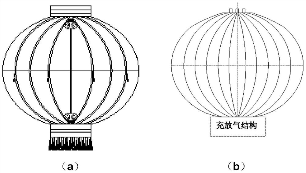
technical field [0001] The invention relates to a design scheme of a fast inflation and deflation device for a palace lantern for celebrations, and belongs to the technical field of space flexible deployment systems. Background technique [0002] The structure of the celebration palace lantern is shown as figure 1 As shown, it is composed of an outer skin (a) and an inner tank (b), and the inflation and deflation structure is connected under the inner tank. The outer skin is mainly used to maintain the shape of the palace lantern, bear the force, provide mooring points and beautify the decoration, and the inner tank is used to seal and generate lift. The flexible film interface is extended out of the liner and connected with the inflatable device. The inflatable device inflates helium into the liner through the flexible film, and the flexible film interface is fastened with a tether. [0003] The filling and deflation structure in the original design scheme is as follows: ...

Claims


Application Information

Patent Timeline
Patent Type & Authority Applications(China)
IPC IPC(8): F17C7/00F17C13/00F17C13/04F17C13/02
CPCF17C7/00F17C13/00F17C13/04F17C13/025F17C2205/0302F17C2221/017F17C2227/041F17C2250/043F17C2250/0626F17C2250/075
Inventor 董海波王立武滕海山陈旭廖航李博
Owner BEIJING RES INST OF SPATIAL MECHANICAL & ELECTRICAL TECH
Why Eureka
Try Eureka