Reflector antenna based on three-telescopic-rod driving and quasi-geodesic line grid structure

A technology of grid structure and reflective surface, which is applied to antennas, foldable antennas, retractable units, etc., can solve the problems that the quadrilateral structure affects the accuracy of the antenna shape and surface, is unfavorable for the promotion and use of large-diameter antennas, and technical difficulties are difficult to overcome. Maintenance and replacement, simple structural layout rules, simple and convenient control

Active Publication Date: 2021-03-02
XIDIAN UNIV
View PDF16 Cites 3 Cited by
  • Summary
  • Abstract
  • Description
  • Claims
  • Application Information

AI Technical Summary

Problems solved by technology

The defect of this invention is that the complex truss structure leads to complex manufacturing and high weight, and the instability of the quadrilateral structure will affect the shape and surface accuracy of the antenna; at the same time, the processing and manufacturing of various types of truss structures is difficult, and the forming process is too complicated. complex
Due to the limitation of weight and manufacturing difficulty, it is more and more difficult to overcome the technical difficulty of continuing to expand the diameter of the reflector, so it is not conducive to the further promotion and use of large-diameter antennas

Method used


Image

  • Reflector antenna based on three-telescopic-rod driving and quasi-geodesic line grid structure
  • Reflector antenna based on three-telescopic-rod driving and quasi-geodesic line grid structure
  • Reflector antenna based on three-telescopic-rod driving and quasi-geodesic line grid structure

Examples


Embodiment 1

[0030] Embodiment 1, the main reflection surface of this embodiment adopts a triangular light metal plate.

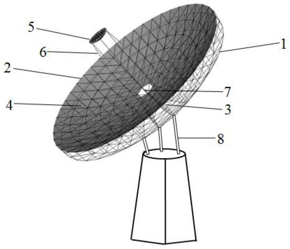
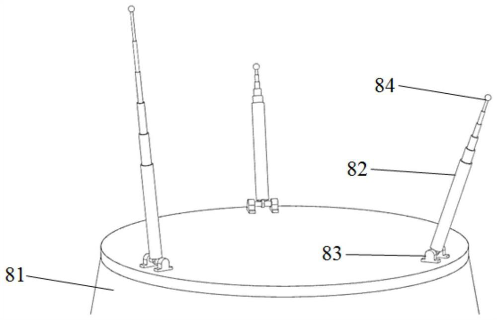
[0031] refer to figure 1 , the present invention includes a support back frame 1, a reflection surface skeleton 2, a vertical connecting rod 3, a main reflection surface 4, a secondary reflection surface 5, a radial support rod 6, a feed source 7 and an attitude control device 8, wherein:

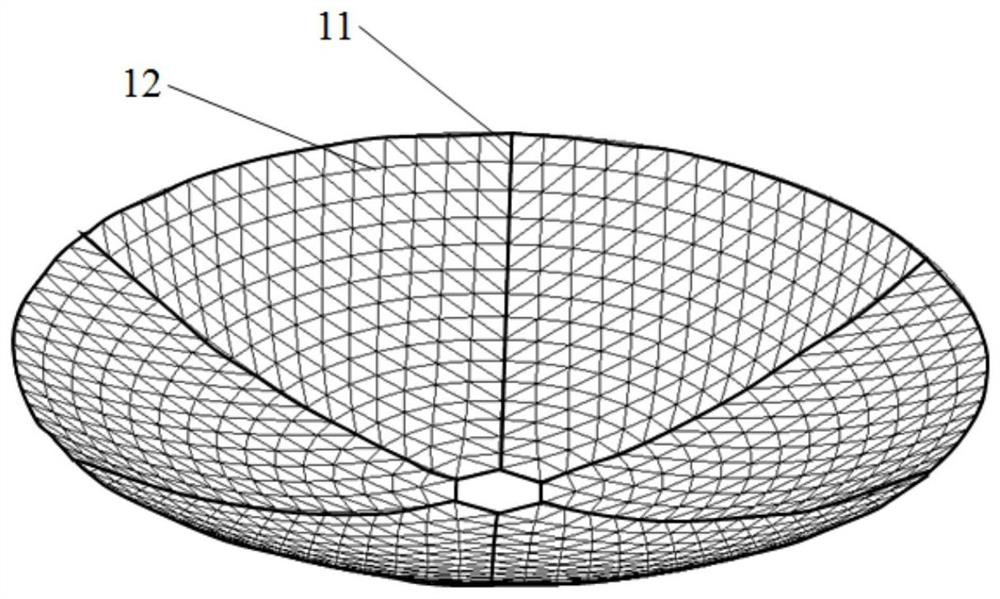
[0032] The support back frame 1, its structural schematic diagram refers to figure 2 , using a parabolic truss structure including a supporting main back frame 11 and a supporting secondary back frame 12, the supporting main back frame 11 adopts a truss structure formed by connecting a plurality of first main rods and a plurality of first main joint balls, It includes an inner ring frame, an outer ring frame, and N radial frames distributed between the inner ring frame and the outer ring frame and arranged radially and uniformly; the supporting sub-back frame 12 includes N quasi-ge...

Embodiment 2

[0040] Embodiment 2. The main reflection surface of this embodiment adopts a trapezoidal light metal plate, and other structures are the same as those of Embodiment 1.

[0041] The main reflector 4 is composed of a trapezoidal light metal plate; the main reflector 4 is spliced ​​in an array of concentric circles with the apex of the reflector skeleton 2 as the center, and the number of circumferential arrays is the same as the circumferential equal fraction of the reflector. The number of radial layers in the array is the same as the number of radial sub-rings of the reflective surface, and the number of trapezoidal panels in each radial layer in each array is selected from one of 1, 2, and 4 according to the maximum area of ​​the trapezoid , that is, when the number of trapezoidal panels in the radial layer is 1, and the maximum area of ​​the trapezoid exceeds the area limit, then the number of trapezoidal panels in the radial layer is 2; when the number of trapezoidal panels ...


PUM


Abstract

The invention provides a reflector antenna based on three-telescopic-rod driving and a quasi-geodesic line grid structure, and aims to reduce the mass of the reflector antenna and reduce the construction cost while ensuring the profile precision of the reflector antenna. The reflector antenna comprises a supporting back frame, a reflecting surface framework, a vertical connecting rod, a main reflecting surface, an auxiliary reflecting surface, a radial supporting rod, a feed source and an attitude control device, wherein the supporting back frame and the reflecting surface framework adopt a paraboloid-shaped truss structure in a quasi geodesic line grid form; the supporting back frame is connected with the reflecting surface framework through a vertical connecting rod; the main reflectingsurface is fixed on a quasi geodesic grid of the reflecting surface framework; the auxiliary reflecting surface is fixed at the focus position of the main reflecting surface through a radial supporting rod; the feed source is fixed at the vertex position of the reflecting surface framework; and the attitude control device comprises a base and telescopic rods, the bottom end of each telescopic rodis connected with the base through a revolute pair connecting structure, and the top end of each telescopic rod is connected with the supporting back frame through a spherical pair connecting structure.

Description

technical field [0001] The invention belongs to the technical field of antennas, and relates to a reflector antenna, in particular to a reflector antenna driven by three telescopic rods and a quasi-geodetic grid structure. Background technique [0002] The reflector antenna is a precision instrument that mainly receives electromagnetic radiation. It can also radiate electromagnetic waves outward. It can achieve large aperture and narrow beam. It has the characteristics of high resolution and high sensitivity. It is widely used in radio astronomy, radar, communication and space detection, etc. field. [0003] The traditional reflector antenna adopts a solid surface structure made of rigid panels to meet the development needs of communication applications. The antenna diameter is getting bigger and bigger. Due to the serious deformation caused by factors such as self-weight, temperature and wind load in a complex environment, it makes The accuracy of the antenna reflective su...

Claims


Application Information

Patent Timeline
Patent Type & Authority Applications(China)
IPC IPC(8): H01Q15/14H01Q15/16H01Q19/18H01Q1/12H01Q1/10
CPCH01Q15/14H01Q15/16H01Q19/18H01Q1/125H01Q1/10H01Q3/08H01Q19/19
Inventor 郑飞颜立德陈梅芮喜
Owner XIDIAN UNIV
Why Eureka
Try Eureka