
A high-speed dfb laser chip and its manufacturing method

A technology of DFB lasers and manufacturing methods, which is applied in the direction of lasers, semiconductor lasers, phonon exciters, etc., can solve the problems of increasing photon energy loss, reducing chip reliability, and reducing chip life, so as to meet high-speed modulation applications and reduce ionization. Effects of bombardment damage and package yield improvement

Active Publication Date: 2022-07-08
湖北光安伦芯片有限公司
View PDF7 Cites 0 Cited by
  • Summary
  • Abstract
  • Description
  • Claims
  • Application Information

AI Technical Summary

Problems solved by technology

[0003] In the prior art, for the fabrication of BCB with RWG (ridge waveguide) structure, BCB is usually used to fill all the grooves on both sides of the ridge waveguide, then use ion etching to planarize the height of BCB and ridge waveguide, and finally perform window injection This kind of BCB pattern structure is likely to cause heat accumulation during the working process of the laser chip, increase photon energy loss and reduce optical gain, thereby reducing chip life, and also cause ion damage to the surface of the ridge waveguide during the ion etching process, reducing the chip reliability
Therefore, although the BCB manufacturing method using the RWG structure improves the laser modulation rate, the yield rate is not high, and it cannot meet the market demand for operating temperature.

Method used


Image

  • A high-speed dfb laser chip and its manufacturing method
  • A high-speed dfb laser chip and its manufacturing method
  • A high-speed dfb laser chip and its manufacturing method

Examples


Embodiment Construction

[0044] The technical solutions in the embodiments of the present invention will be described clearly and completely below. Obviously, the described embodiments are only a part of the embodiments of the present invention, rather than all the embodiments. Based on the embodiments of the present invention, all other embodiments obtained by persons of ordinary skill in the art without creative efforts shall fall within the protection scope of the present invention.

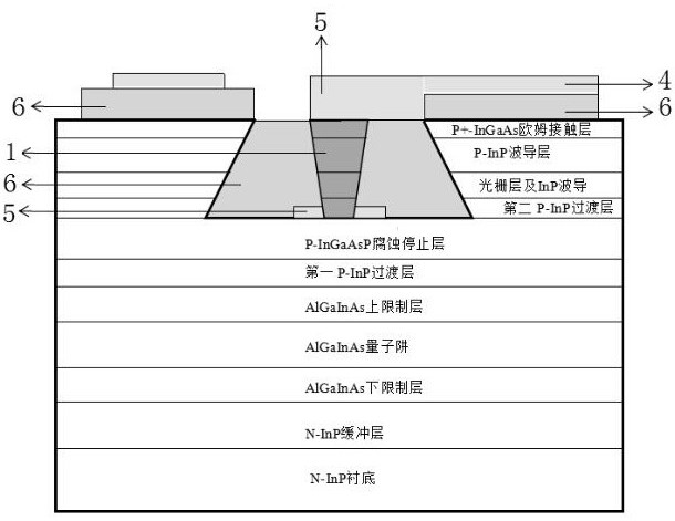
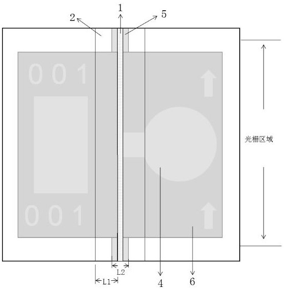
[0045] see figure 1 and figure 2 , an embodiment of the present invention provides a high-speed DFB laser chip, including a laser structure, the laser structure shown is grown on a substrate, the upper surface of the laser structure is provided with a ridge waveguide and grooves on both sides of the ridge waveguide, the A first electrode is arranged on the top layer of the ridge waveguide, BCB patterns are arranged on both sides of the ridge waveguide, the thickness of the BCB in the groove is consistent with the he...


PUM

PropertyMeasurementUnit
depthaaaaaaaaaa

Abstract

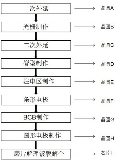
The invention relates to a high-speed DFB laser chip and a manufacturing method thereof, comprising the following steps: sequentially growing a buffer layer, a lower confinement layer, a quantum well, an upper confinement layer, a first transition layer, an etching stop layer, a second The transition layer, grating layer, P-InP cladding layer, after the grating is fabricated, the P-InP waveguide layer and the ohmic contact layer are epitaxially grown again, and then the ridge waveguide fabrication and the electrical injection window contact bar fabrication on the ridge bar are completed. A strip electrode is made on the strip, and BCB patterns are made on both sides of the ridge waveguide. The thickness of the BCB in the groove is etched to be the same as the height of the ridge waveguide. A circular electrode is made on the BCB pattern to connect the strip electrodes. The invention not only effectively reduces various parasitic capacitances of the laser, satisfies the application of high-speed modulation, but also reduces the ion bombardment damage to the ridge waveguide during the existing BCB etching process and the pressure loss risk to the ridge waveguide during the later packaging process of the chip, and improves the packaging process. yield, while avoiding cavity surface damage caused by photon heat accumulation on the cavity surface.

Description

technical field [0001] The invention belongs to the technical field of high-speed optical communication chips, and in particular relates to a high-speed DFB laser chip and a manufacturing method thereof. Background technique [0002] With the continuous progress of information technology, people's requirements for optical communication bandwidth are getting higher and higher. At present, the RC parameter f can be reduced by introducing the BCB process. c =(1 / 2πRC), thereby effectively reducing various parasitic capacitances of the laser to meet high-speed modulation applications. [0003] In the prior art, for the BCB fabrication of the RWG (ridge waveguide) structure, the trenches on both sides of the ridge waveguide are usually filled with BCB, then ion etching is used to planarize the height of the BCB and the ridge waveguide, and finally the window is injected into the window. This kind of BCB pattern structure is easy to cause heat accumulation during the working proce...

Claims


Application Information

Patent Timeline
Patent Type & Authority Patents(China)
IPC IPC(8): H01S5/20H01S5/22
CPCH01S5/2018H01S5/204H01S5/22H01S5/2206
Inventor 李紫谦张恩黄鹤许海明
Owner 湖北光安伦芯片有限公司
Learn More