Laminated Busbar Structures for Discrete Parallel and Modular Applications

A technology of laminated busbars and discrete devices, applied in semiconductor devices, electric solid state devices, structural components of conversion equipment, etc., can solve problems such as current imbalance of parallel devices, structural asymmetry, and unequal connection paths between diodes and capacitors. , to reduce the connection path, facilitate assembly and maintenance, and achieve the effect of wide applicability

Active Publication Date: 2021-09-21
HEFEI UNIV OF TECH
View PDF7 Cites 0 Cited by
  • Summary
  • Abstract
  • Description
  • Claims
  • Application Information

AI Technical Summary

Problems solved by technology

[0006] 1. The structure does not consider the modular application of the laminated busbar structure;
[0007] 2. The structure does not consider the symmetrical layout
[0009] 1. The number of diodes in the integrated laminated busbar of this structure is not even, the structure is asymmetrical, there is spare space in the crimping structure, and the space utilization rate is not high;
[0010] 2. The connection paths between diodes and capacitors in this structure are not equal, and the current of parallel devices is unbalanced.

Method used


Image

  • Laminated Busbar Structures for Discrete Parallel and Modular Applications
  • Laminated Busbar Structures for Discrete Parallel and Modular Applications
  • Laminated Busbar Structures for Discrete Parallel and Modular Applications

Examples


Embodiment Construction

[0034]The technical solutions of the present invention will be clearly and completely described below in conjunction with the accompanying drawings.

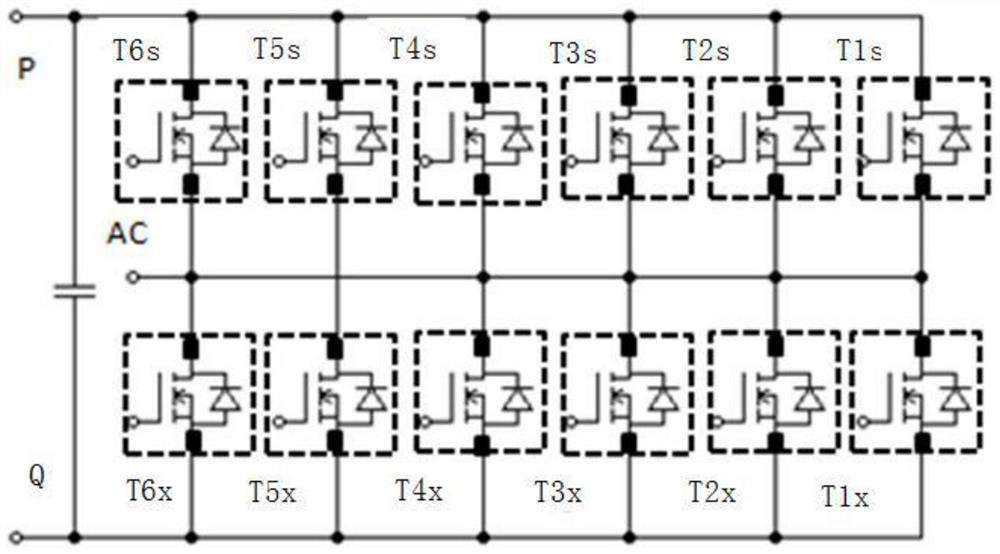
[0035] figure 1 It is a circuit topology diagram of the package structure 45 in the embodiment of the present invention. It can be seen from the diagram that in this embodiment, N is a positive integer. Specifically, N=6 is selected. That is, the packaging structure 45 includes six bridge arms and 12 power devices, which are respectively upper bridge arm power devices T1s, T2s, T3s, T4s, T5s, T6s and lower bridge arm power devices T1x, T2x, T3x, T4x, T5x, T6x. Each bridge arm is composed of an upper bridge arm power device and a lower bridge arm power device in series, and then the six bridge arms are connected in parallel, and the six upper bridge arm power devices are connected to the positive pole P of the DC power supply and the AC output terminal, six Each of the lower bridge arm power devices is connected to the negative ...


PUM


Abstract

The invention relates to a laminated busbar structure suitable for parallel connection and modular application of discrete devices, belonging to the technical field of semiconductor devices. The laminated busbar includes an AC output busbar, a positive busbar and a negative busbar, wherein the negative busbar is used to connect the power device of the lower bridge arm and the negative terminal of the capacitor module, and the positive busbar is used to connect the power device of the upper bridge arm As well as the positive terminal of the capacitor module, the AC output busbar is connected to the positive busbar through the power device of the upper bridge arm, and connected to the negative busbar through the power device of the lower bridge arm. A laminated busbar structure suitable for parallel connection is formed by combining multiple laminated busbar units and multiple sets of discrete devices, which reduces the parasitic inductance and the difference in inductance of each branch is small, and can be reduced by increasing the number of devices in the vertical direction It is suitable for various current levels, and the entire busbar structure can be copied horizontally to form a three-phase system, which is convenient for assembly and maintenance. This modular feature makes the patented busbar structure more widely applicable.

Description

technical field [0001] The invention relates to the technical field of semiconductor devices, in particular to a laminated busbar structure suitable for parallel connection and modular application of discrete devices. Background technique [0002] In high-power power electronic devices, power semiconductor devices are electrically connected to capacitor modules and AC terminals through laminated busbars. However, unreasonable busbar structure design will bring a large parasitic inductance, and then generate a large voltage overshoot during the turn-off transient of the power device, which poses a threat to the safe operation of the device. And with the gradual use of devices with fast on-off capabilities, such as SiC MOSFETs, the same level of parasitic inductance will bring greater overvoltage, so it is particularly important to develop a busbar structure with low parasitic inductance. [0003] The current carrying capacity of a single discrete device is low. In order to i...

Claims


Application Information

Patent Timeline
Patent Type & Authority Patents(China)
IPC IPC(8): H02M7/00H02M7/5387H01L23/48
CPCH01L23/48H02M7/003H02M7/5387H01L2924/1815
Inventor 於少林王佳宁王琛吴馥晨刘元剑
Owner HEFEI UNIV OF TECH
Why Eureka
Try Eureka