Valve prosthesis device implanted into heart
A valve prosthesis and valve technology, applied in the field of medical devices, can solve problems such as the relative reduction of ejection fraction, and achieve the effects of improving heart failure, reducing tension, and reducing myocardial oxygen consumption
- Summary
- Abstract
- Description
- Claims
- Application Information
AI Technical Summary
Problems solved by technology
Method used
Image

Examples
Embodiment 1
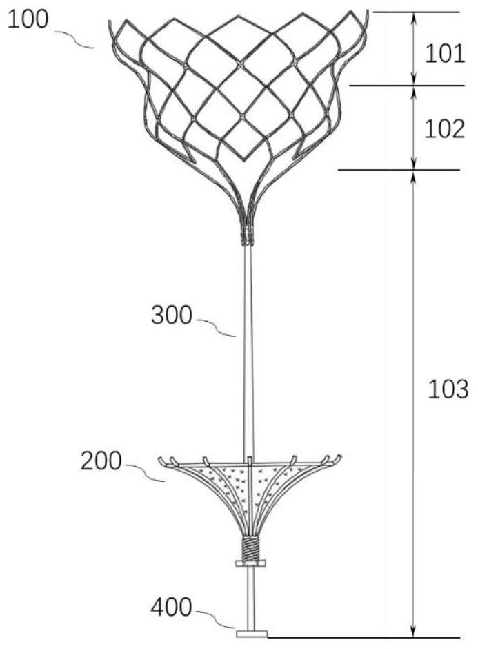
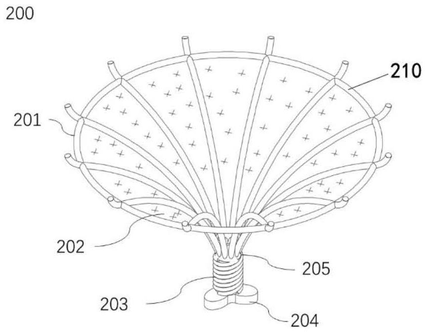
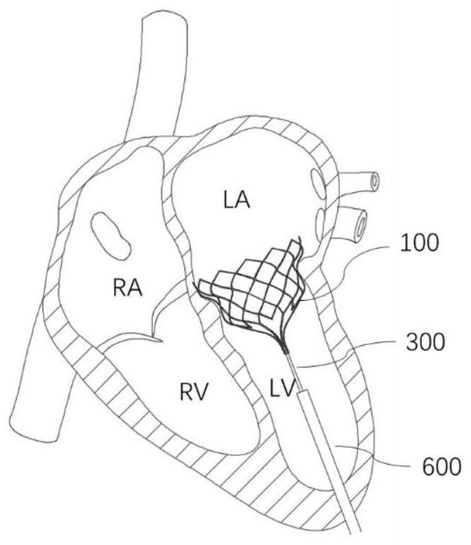
[0042] This embodiment provides a valve prosthesis device for implanting into the heart, including a valve body 100 and a ventricular volume reducer 200, the valve body 100 includes a valve support 110 and an artificial valve attached to the valve support 110 leaves; the ventricular volume reducing element 200 is fixed to the valve main body 100 through a connecting piece 300, and the ventricular volume reducing element 200 is arranged in a manner to form an isolation cavity 500 that reduces the volume of the ventricle between the inner wall of the apex; wherein, the After the prosthetic device is implanted in the heart, the valve main body 100 is released at the original valve annulus to replace the original valve to open or close the blood channel, and the ventricular volume reducing element 200 is released to the left ventricle for Improve left ventricular enlargement caused by mitral regurgitation.
[0043] The heart valves in the prior art are only used to replace the nat...
Embodiment 2
[0062] This embodiment provides a valve prosthesis device for implanting into the heart. The prosthesis device in this embodiment is similar to the prosthesis device in Embodiment 1, except for the structure of the ventricular volume reducing element 200 . Wherein, the ventricular volume reducing element 200 described in this embodiment is configured as a disc-shaped structure, and the ventricular volume reducing element 200 of the disc-shaped structure is radially attached to the inner wall of the apex of the heart to form the isolation cavity 500 .
[0063] see Figure 6 , Figure 7 , is a schematic structural view of the valve prosthesis device of this embodiment.
[0064] Compared with the inverted conical structure, the distance from the apex of the heart after the release of the ventricular volume reducing member 200 in this embodiment is relatively long, so it can prevent the inner wall of the apex from touching the ventricular volume reducing member 200 when the heart...
Embodiment 3
[0068] This embodiment provides a valve prosthesis device for implanting into the heart. The prosthesis device of this embodiment is similar to the prosthesis device of Embodiment 1, and the ventricular volume reducing member 200 is in an inverted cone shape, and the difference lies in the anchoring device structure, the anchoring device of this embodiment includes a second anchoring portion 207, wherein the second anchoring portion 207 is arranged in the circumferential direction of the ventricular volume reducing element 200, and the second anchoring portion 207 provides anchoring force by piercing into the inner wall of the apex, Instead of attaching to the outer wall of the ventricle in Example 1.
[0069] Specifically, see Figure 8 , the large-diameter end portion 210 of the frame body 201 is in contact with the inner wall of the ventricle, and the force dissipating device 204 of the frame body 201 is in contact with the apex of the heart, so the second anchoring portion...
PUM
 Abstract
Description
Claims
Application Information
 - R&D
- Intellectual Property
- Life Sciences
- Materials
- Tech Scout
- Unparalleled Data Quality
- Higher Quality Content
- 60% Fewer Hallucinations
Browse by: Latest US Patents, China's latest patents, Technical Efficacy Thesaurus, Application Domain, Technology Topic, Popular Technical Reports.
© 2025 PatSnap. All rights reserved.Legal|Privacy policy|Modern Slavery Act Transparency Statement|Sitemap|About US| Contact US: help@patsnap.com