Ventilation device for blood disease patient ward

A ventilation device and patient technology, applied in the field of ward ventilation, can solve the problems of low immunity, easy to be infected, cross-infection of patients, etc., and achieve the effect of protecting system operation and management personnel, preventing diffusion, and improving indoor airflow

Pending Publication Date: 2021-03-09
NANYANG CITY CENT HOSPITAL
View PDF9 Cites 1 Cited by
  • Summary
  • Abstract
  • Description
  • Claims
  • Application Information

AI Technical Summary

Problems solved by technology

[0003] In the prior art, the main purpose of ventilating the ward is to remove the waste gas in the ward and ensure the necessary amount of fresh air in the ward. However, there are a lot of bacteria and dust in the air. Under normal circumstances, because the human body has immunity, it will not Infected by bacteria, however, patients with blood diseases have relatively low immunity and are prone to infection. At the same time, there are usually multiple patients in the ward. If the ventilation effect is poor, it will also lead to cross-infection between patients. Through the above The explanation of the two situations shows that it is necessary to disinfect and sterilize the air entering the ward in a timely and effective manner to ensure that patients are not infected

Method used


Image

  • Ventilation device for blood disease patient ward
  • Ventilation device for blood disease patient ward
  • Ventilation device for blood disease patient ward

Examples


Embodiment 1

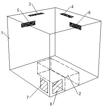
[0035] combine figure 1 , a kind of ventilation device for blood disease patient ward, comprises ward 1 and the sick bed 2 that is arranged in ward 1, comprises the air supply mechanism that is arranged on the top of ward 1 and the exhaust mechanism that is arranged on the bottom of ward 1.

[0036] The air supply mechanism includes an air supply outlet 3 located on the top of the ward 1, facing the end of the bed 2, and an air supply outlet 3 4 at the side of the bed 2, located on the side of the ward 1. wall, facing the air outlet two 5 at the end of the bed 2, the air outlet four 6 facing the bedside of the hospital bed 2, the air outlet one 3, the air outlet two 5, the air outlet three 4 and the air outlet four 6 There are air supply components everywhere.

[0037] The exhaust mechanism includes an air exhaust outlet 7 located at the bottom of the ward 1, on the wall of the ward 1 corresponding to the bedside of the hospital bed 2, and on the side wall of the ward 1 corre...

Embodiment 2

[0041] On the basis of Example 1, under stable conditions, the ventilation efficiency W in the ward satisfies: W=C e / C i , C e is the pollutant concentration at the exhaust outlet (mol / m 3 ), C i is the concentration of pollutants in the ward (mol / m 3 ).

[0042] The pollutant flow E (mol / s) at the exhaust outlet satisfies: E=v·C e ·a·b, v is the average wind speed (m / s) at the exhaust outlet, a and b are the length (m) and height (m) of the exhaust button respectively.

[0043] Due to the presence of pollutant concentration gradients, the concentration of pollutants in areas close to patients is relatively high, and medical staff should keep an appropriate distance from them when caring for patients. CO within the personnel work area 2 The concentration is 0.029mol / m 3 -0.039mol / m 3 Between, the ventilation efficiency in the ward is the best at this time.

Embodiment 3

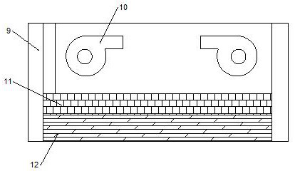
[0045] to combine figure 2 and image 3 , the air supply assembly includes a shroud 9 arranged on the outer top of the ward 1 and communicating with the inside of the ward 1 , inside the shroud 9 , along the direction from the outside of the ward 1 to the inside, a first fan 10 , Primary effect filter 11 and air supply plate 12.

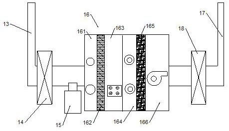
[0046] The air exhaust assembly includes an air inlet pipe 13 connected to the room of the ward 1 and an air outlet pipe 17 connected to the outside of the ward 1. The air inlet pipe 13 and the air outlet pipe 17 are communicated with each other through a sterilizing assembly, and the sterilizing assembly includes Both ends are respectively connected to the treatment chamber 16 of the air inlet pipe 13 and the air outlet pipe 17. The inside of the treatment chamber 16 is provided with an ultraviolet lamp cavity 161 and a medium-efficiency filter 162 in sequence along the direction from the air inlet pipe 13 to the air outlet pipe 17. , the second ...


PUM


Abstract

The invention relates to a ventilation device for a blood disease patient ward. The ventilation device comprises a ward, a sickbed arranged in the ward, an air supply mechanism and an air exhaust mechanism, wherein the air supply mechanism comprises a first air supply outlet and a third air supply outlet which are formed in the top end of the ward, and a second air supply outlet and a fourth air supply outlet which are formed in the side wall of the ward, air supply assemblies are arranged on the first air supply outlet, the second air supply outlet, the third air supply outlet and the fourthair supply outlet, the air exhaust mechanism comprises a first air exhaust opening and a second air exhaust opening which are formed in the bottom of the ward, and air exhaust assemblies are arrangedon the first air exhaust opening and the second air exhaust opening. According to the ventilation device, the combined air supply mechanism and the air exhaust mechanism are adopted, indoor air flow is improved, a pollution source is located at the position close to the air exhaust openings, meanwhile, induced air flow is formed between the air supply openings and the air exhaust openings, indoorpolluted air can be removed easily, medical staff can be better protected, and the induced air flow formed by air supply can be used for conveying polluted air to the air exhaust openings to remove polluted air.

Description

technical field [0001] The invention belongs to the technical field of ward ventilation, and in particular relates to a ventilation device for a ward of blood patients. Background technique [0002] Hematological diseases refer to diseases that originate in the hematopoietic system, or affect the hematopoietic system accompanied by abnormal blood changes, and are characterized by anemia, bleeding, and fever. With the continuous development of science and technology, the efficacy of bone marrow transplantation in the treatment of hematological malignancies, aplastic anemia, paroxysmal nocturnal hemoglobinuria and other congenital or hereditary diseases has been continuously improved; The curative effect of protein / anti-lymphocyte globulin in the treatment of severe aplastic anemia has been greatly improved. However, most patients with blood diseases have low immunity and neutropenia, coupled with the influence of radiotherapy and chemotherapy, they are often prone to infecti...

Claims


Application Information

Patent Timeline
Patent Type & Authority Applications(China)
IPC IPC(8): F24F7/003F24F7/007F24F8/108F24F8/22
CPCF24F3/16F24F7/007
Inventor 陈志鑫
Owner NANYANG CITY CENT HOSPITAL
Why Eureka
Try Eureka