Mammary gland bracket

A breast and electric push rod technology, applied in the field of medical equipment, can solve the problems of not being able to adjust the distance between massage cups, not being able to fold and store, and attaching dust, etc., to achieve the effects of expanding practicability, reducing cleaning times, and facilitating storage

Inactive Publication Date: 2021-03-12
孟文
View PDF0 Cites 0 Cited by
  • Summary
  • Abstract
  • Description
  • Claims
  • Application Information

AI Technical Summary

Problems solved by technology

[0004] When the existing breast bracket is not in use, it cannot be folded and stored. If it is placed outside for a long time, it is easy to be damaged and attached to dust, and the distance between the massage cups cannot be adjusted, so it cannot be applied to users of different physiques. greater limitations

Method used


Image

  • Mammary gland bracket
  • Mammary gland bracket
  • Mammary gland bracket

Examples


Embodiment 1

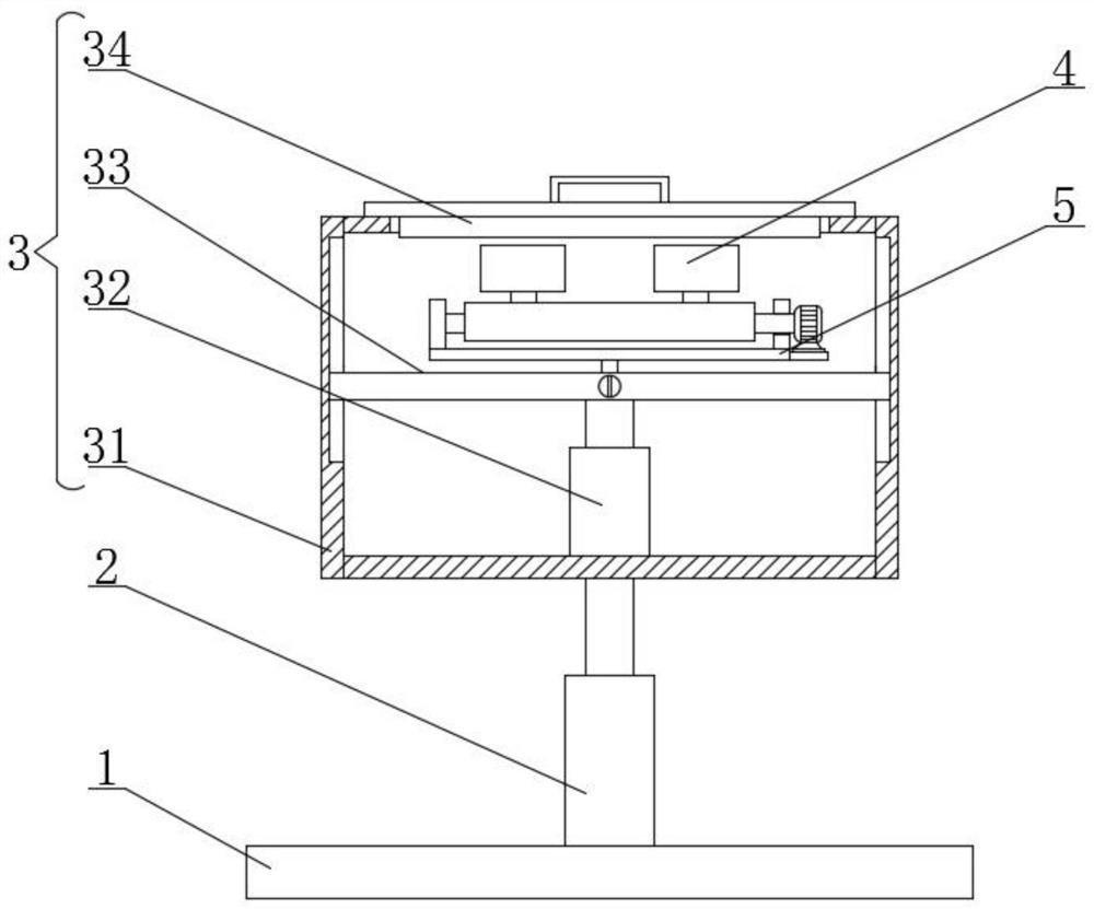
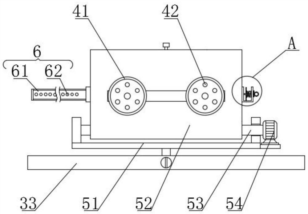
[0032] see Figure 1-8 , the present invention provides a technical solution: a mammary gland bracket, a fixed plate 1; a first electric push rod 2, the first electric push rod 2 is fixedly welded at the center of the top surface of the fixed plate 1; a storage mechanism 3, The storage mechanism 3 includes a storage frame 31, a second electric push rod 32, a placement plate 33 and a sealing cover 34. The top of the first electric push rod 2 is fixedly welded with the storage frame 31, and the bottom of the inner wall of the storage frame 31 is A second electric push rod 32 is fixedly welded in the center, and a placement plate 33 is fixedly welded on the top of the second electric push rod 32, and a sealing cover 34 is connected to the top of the storage frame 31; the moving mechanism 7, the placement The inside of the plate 33 is fixedly equipped with a moving mechanism 7; a rotating mechanism 5, the rotating mechanism 5 includes a mounting seat 51, a rotating plate 52, a fix...

Embodiment 2

[0034] As a preferred solution of Embodiment 1, the connecting device 83 includes a fixed sleeve 831, a sliding plate 832, a second spring 833, a fixed frame 834, an insertion rod 835 and a push rod 836, and the surface of the second threaded sleeve 85 A fixed sleeve 831 is fixedly welded. The end of the fixed sleeve 831 away from the second threaded sleeve 85 passes through the rotating plate 52 and extends to the outside of the rotating plate 52. The top surface of the fixed sleeve 831 extending to the outside of the rotating plate 52 is fixedly welded with A fixed frame 834, a sliding plate 832 is slidably connected between the inner walls of the fixed frame 834, and a second spring 833 is fixedly welded between the top of the sliding plate 832 and the inner wall top of the fixed frame 834, and the sliding plate 832 A push rod 836 is fixedly welded at the center of the bottom, the bottom of the push rod 836 passes through the fixed frame 834 and the fixed sleeve 831 and exte...

Embodiment 3

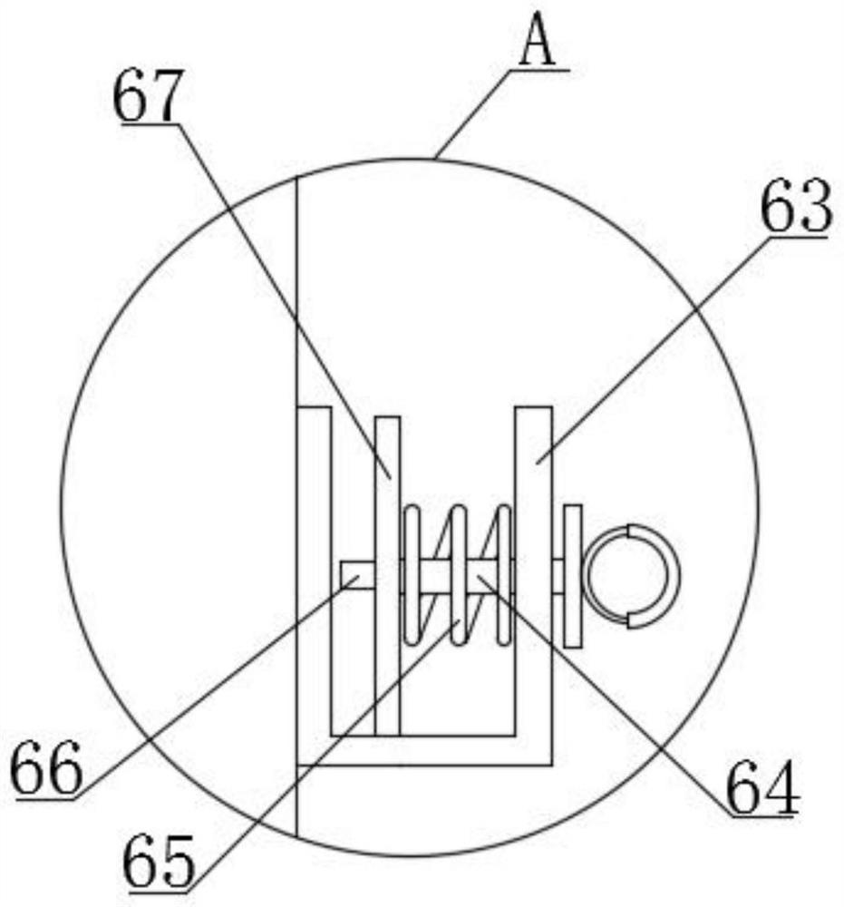
[0036] As a preferred solution of Embodiment 1, the side wall is fixedly installed with a limit mechanism 6, and the limit mechanism 6 includes a strap 61, a through hole 62, a limit frame 63, a sliding rod 64, a first spring 65, a limit A position column 66 and a limit plate 67, a strap 61 is fixedly installed in the center of one side wall of the rotating plate 52, and a plurality of through holes 62 are provided in the inside of the strap 61, and the side of the rotating plate 52 The wall and the side away from the strap 61 are fixedly welded with a limit frame 63, and the center of the side of the limit frame 63 away from the rotating plate 52 is movably inserted with a sliding rod 64, and the slide rod 64 is located at the limit frame 63. One end of the interior is fixedly welded with a limiting plate 67, and the end of the limiting plate 67 away from the sliding rod 64 is fixedly welded with a limiting column 66 that is compatible with the through hole 62, and the surface...


PUM


Abstract

The invention discloses a mammary gland bracket, which comprises a fixing plate. a first electric push rod which is fixedly welded to the center of the top surface of the fixing plate; a storage mechanism, which comprises a storage frame, a second electric push rod, a placement plate and a sealing cover, wherein the storage frame is fixedly welded to the top of the first electric push rod, the second electric push rod is fixedly welded to the middle of the bottom of the inner wall of the storage frame, the placement plate is fixedly welded to the top of the second electric push rod, and the top of the storage frame is connected with a sealing cover in a matched mode; and a moving mechanism which is fixedly mounted in the placement plate. The mammary gland bracket effectively solves the problems that: when not used, an existing mammary gland bracket cannot be folded and stored and is prone to damage and causes dust attachment after standing outside for a long time, and the distance between massage cups cannot be adjusted, so that the existing mammary gland bracket cannot be suitable for users with different physiques and has large limitation.

Description

technical field [0001] The invention relates to the technical field of medical devices, in particular to a mammary gland bracket. Background technique [0002] The mammary gland is located between the superficial and deep layers of the subcutaneous superficial fascia. The superficial fascia stretches into the mammary gland tissue to form a cord-like lobular septum. One end is connected to the pectoralis fascia, and the other end is connected to the skin to fix the mammary gland to the chest. In the subcutaneous tissue of the breast, mammary gland hyperplasia refers to the hyperplasia of breast epithelium and fibrous tissue, the structural degeneration of breast tissue ducts and lobules, and the growth of progressive connective tissue. It is the most common breast disease in women. Massage can promote breast blood circulation and is an effective means to prevent breast hyperplasia. [0003] However, there are some disadvantages in the traditional use process, such as: [00...

Claims


Application Information

Patent Timeline
Patent Type & Authority Applications(China)
IPC IPC(8): A61H15/00A61H7/00
CPCA61H7/00A61H15/0078A61H2201/0161A61H2201/1621A61H2205/082
Inventor 孟文
Owner 孟文
Why Eureka
Try Eureka