
Suction cylinder steel pipe machining and manufacturing technology for suction type jacket

A suction cylinder and jacket technology, applied in metal processing, metal processing equipment, applications, etc., can solve the problems of large fluctuations in manual welding quality, difficulty in ensuring welding quality, and difficulty in ensuring dimensional accuracy, so as to reduce offshore construction risks, The layout of the production process is reasonable and the effect of increasing the scope of application

Inactive Publication Date: 2021-03-12
HEFEI ZIKING PIPE INC
View PDF12 Cites 1 Cited by
  • Summary
  • Abstract
  • Description
  • Claims
  • Application Information

AI Technical Summary

Problems solved by technology

[0005] Due to the relatively large diameter and thickness of the existing suction tube steel pipe, the steel tube collapses due to its own weight, and the tube body is easily deformed. During the production, processing and transfer process, it is difficult to ensure the dimensional accuracy of the tube body, such as ellipticity and butt misalignment.
[0006] For the processing of single-section steel pipes of the existing suction tube steel pipes, the vertical assembly is generally selected after rolling the arc section, and the dimensional accuracy control of the vertical assembly is relatively easy. The factors fluctuate greatly, and the welding quality is difficult to guarantee
The diameter of the barrel joint is large, generally above 10,000mm, the efficiency is low during welding, and the dimensional accuracy is difficult to guarantee during the assembly and transfer process

Method used


Image

  • Suction cylinder steel pipe machining and manufacturing technology for suction type jacket
  • Suction cylinder steel pipe machining and manufacturing technology for suction type jacket
  • Suction cylinder steel pipe machining and manufacturing technology for suction type jacket

Examples


Embodiment 1

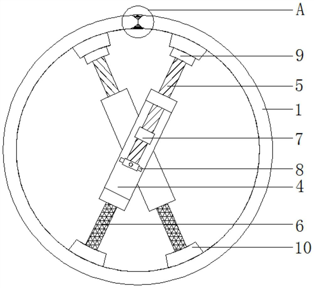
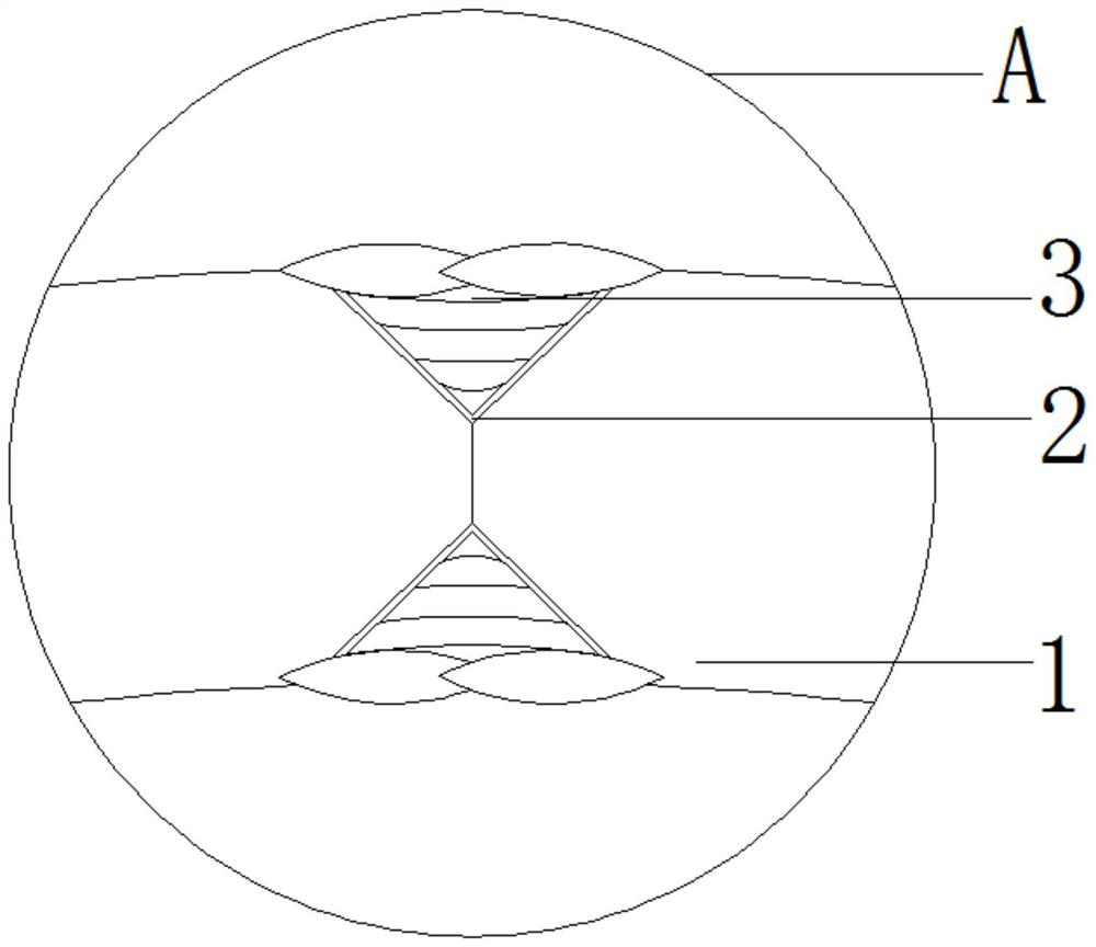
[0025] see Figure 1-2 , a suction tube steel pipe processing technology for a suction jacket, including a suction tube steel tube 1. During the processing of the suction tube steel tube, the steel plates are spliced ​​first, and then rolled. During the rolling process, side supports and top supports are used to assist tooling to prevent The deformation of the cylinder caused by the collapse of the steel pipe due to its own weight, the longitudinal seam submerged arc welding is carried out after the rolling is completed, the two ends of the single-section steel pipe are equipped with well braces and inner reinforcement rings, and the multi-section cylinder is on the special rotating roller with side arms Carry out group pairing and transfer to the welding station with a joint axis car. When welding the circular seam, multiple positions are carried out simultaneously; the welding adopts the single-wire straight seam submerged arc welding technology, that is, the outer welding us...

Embodiment 2

[0037] see figure 1 , the support mechanism used for the suction tube steel tube for the suction jacket includes a concave plate 4, two groups of concave plates 4 are arranged, and the back is connected by rotating shafts, and a screw rod 5 is threaded on the top of the concave plate 4, and The bottom is fixedly connected with a fixed rod 6; the bottom top of the screw rod 5 is threaded and connected with a fixed plate 7, and the bottom end is fixedly connected with a rotating handle 8, the fixed plate 7 is fixedly connected with the concave plate 4, and the upper top of the screw rod 5 is fixedly sleeved. There are bearings 9, and one side of the bearing 9 and the fixed rod 6 is fixedly connected with an arc-shaped plate 10, and the arc-shaped plate 10 is in close contact with the inner wall of the suction tube steel pipe 1; The arc-shaped plate 10 is placed on the inner wall of the suction tube steel pipe 1, and the screw 5 is rotated by adjusting the rotating handle 8. Due ...

Embodiment 3

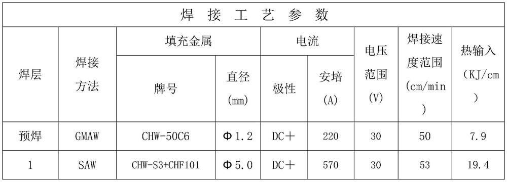
[0040] The process qualification test is carried out on the Q355ND steel plate T=30mm thick test plate, the following is the data of the assessment parameters and physical and chemical experiment analysis after welding. The welding parameters are as follows:

[0041] Table 1 Welding parameters of Q355ND suction cylinder straight seam submerged arc welded steel pipe

[0042]

[0043]

[0044] Table 2 Mechanical performance test of weld seam of Q355ND process qualification test plate

[0045]

[0046]

[0047] Cylinder force data analysis and installation of support

[0048] During the production and transshipment process, the suction cylinder steel pipe 1 has a relatively large diameter and thickness, and will collapse due to the influence of its own weight, resulting in that the roundness of the steel pipe cannot be guaranteed. Therefore, in the single-section production process, it is also necessary to install well braces and inner reinforcement rings on the end...


PUM


Abstract

The invention discloses a suction cylinder steel pipe machining and manufacturing technology for a suction type jacket, and relates to the field of submerged-arc welding steel pipe machining and manufacturing. The suction cylinder steel pipe machining and manufacturing technology involves a suction cylinder steel pipe and comprises the following steps that in the machining process of the suction cylinder steel pipe, steel plates are spliced firstly, and then the steel plates are rolled, in the rolling process, cylinder deformation caused by self-weight collapse of the steel pipe is prevented through side support and top support auxiliary tools, longitudinal seam submerged-arc welding is conducted after rolling is completed, well supports and inner reinforcing rings are additionally arranged at the two ends of a single-section steel pipe, multiple sections of cylinders are assembled on a special rotating roller with side holding arm supports and transferred to a welding station througha combined axis vehicle, during circular seam welding, multiple stations are synchronously carried out. According to the suction cylinder steel pipe machining and manufacturing technology for the suction type jacket, firstly, the steel plates are spliced, after the steel plates are spliced, circular seam grooves are machined, butt joint line deviation is controlled, and it is guaranteed that the misalignment amount of the rolled steel plates meets the technological requirement.

Description

Technical field: [0001] The invention relates to the field of processing and manufacturing submerged arc welded steel pipes, in particular to a technology for processing and manufacturing a suction tube steel pipe for a suction jacket. Background technique: [0002] Wind energy is a clean energy with the characteristics of renewability, availability, long-term, and periodicity. Wind energy has different characteristics from fossil energy such as coal and petroleum. There are no problems such as energy exploration, energy mining, and energy processing. During its use, it will not be reduced due to the increase in usage. The application of wind energy is mainly wind power generation, while offshore wind power will be affected by the marine environment and pile foundation structures. [0003] In addition to the advantages of the traditional steel pipe pile jacket foundation, the suction jacket foundation also has the following advantages: (1) less steel consumption, which can r...

Claims


Application Information

Patent Timeline
IPC IPC(8): B23K9/18B23K9/16B23K9/32B23K9/235B23K9/00B23K37/053
CPCB23K9/18B23K9/16B23K9/32B23K9/235B23K9/0052B23K37/053B23K2101/06B23K2103/04
Inventor 陈明吴宏根彭静万军
Owner HEFEI ZIKING PIPE INC
Learn More