Eureka AIR delivers breakthrough ideas for toughest innovation challenges, trusted by R&D personnel around the world.

Core tube type broken bridge composite wall system for low-energy-consumption building and construction method

A core tube, construction technology, applied in the direction of construction, building components, building structure, etc., can solve the problems of concrete fire protection layer and insulation layer falling off, life and property damage, high construction cost, to increase structural stability and safety. Seismic performance, solving the risk of cracking or falling off, and improving safety performance such as seismic performance

Pending Publication Date: 2021-03-12
崔景新
View PDF0 Cites 0 Cited by
  • Summary
  • Abstract
  • Description
  • Claims
  • Application Information

AI Technical Summary

Problems solved by technology

[0002] Safety impact: The concrete fire protection layer, prefabricated insulation board, and shear wall joints of the main structural layer of the concrete building in the existing low-energy structural insulation integrated building technology are fragile, which can easily cause the concrete fire protection layer and insulation layer to fall off or crack. Causes a great potential safety hazard; because the joints are weak, the anti-seismic performance of the external wall insulation system is very poor. Once an earthquake occurs, the entire concrete fire protection layer and insulation layer will fall off, causing greater damage to life and property
[0003] Impact on energy saving: The existing low-energy-consumption structural insulation integrated building technology has too many connectors between the concrete fire protection layer, the insulation layer and the structural layer, and the connectors are basically made of metal, resulting in a large number of cold bridges on the exterior wall of the building, making the exterior The energy saving effect of the wall is seriously reduced
[0004] The existing low-energy building technology has poor insulation treatment of windows and too many cold bridges, which cannot meet the energy-saving requirements of low-energy buildings. Even if it can barely meet the energy-saving requirements of low energy consumption greater than or equal to 90%, it is necessary to increase window bridge treatment and passive windows. The material and labor consumption make the construction cost very high
[0005] Some of the existing low-energy-consumption structural and thermal insulation integrated building technologies use the floor overhanging technology. Although the risk of falling off the fire protection layer and the thermal insulation layer is solved, the thermal insulation of the outer end of the floor and the cold bridge cannot be properly handled, so that the energy-saving effect of the building can be improved. severe decline
[0006] The existing low-energy structural insulation integration technology does not completely treat the top floor parapet insulation and cold bridge of the building, and the processing method is very complicated, not only the cost is high, but the energy-saving effect is also very poor
[0007] The existing low-energy structural insulation integration technology requires building exterior wall air-conditioning panels and downpipes to be rooted on the main shear wall, and insulation problems and cold bridges cannot be completely resolved, which seriously reduces the building's energy-saving effect
[0008] The prefabricated insulation board of the existing low energy consumption structural insulation integrated building technology is easy to deviate when the prefabricated insulation board is pouring concrete, which affects the quality of the project
[0009] Therefore, the current low energy consumption structural insulation integrated building technology makes it difficult to achieve the requirement of 90% or more for building comprehensive energy saving
Even if it is barely achieved, the cost is huge

Method used


Image

  • Core tube type broken bridge composite wall system for low-energy-consumption building and construction method
  • Core tube type broken bridge composite wall system for low-energy-consumption building and construction method
  • Core tube type broken bridge composite wall system for low-energy-consumption building and construction method

Examples


Embodiment 2

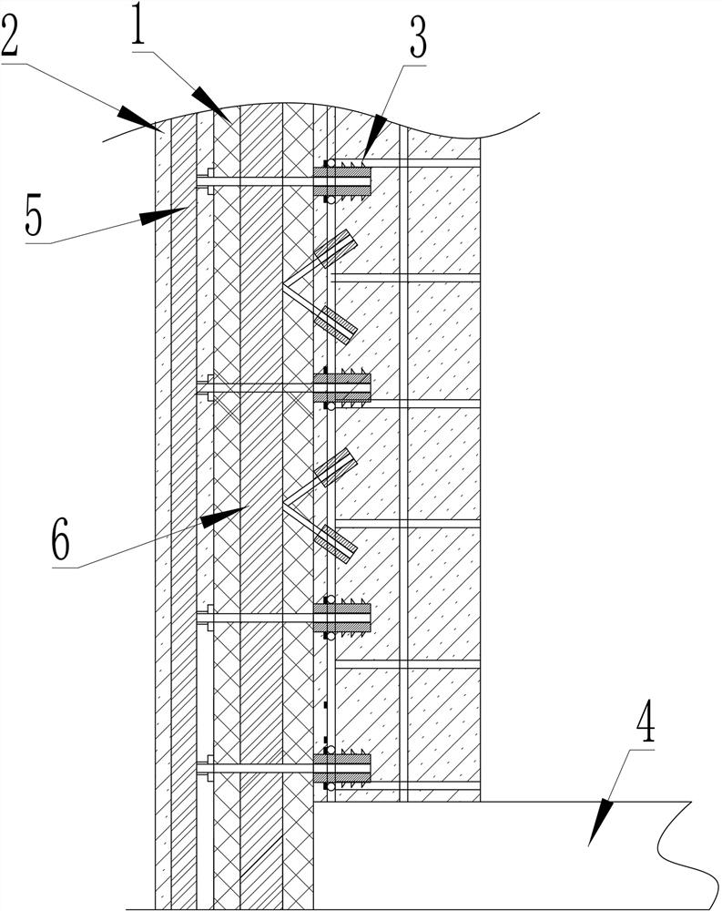
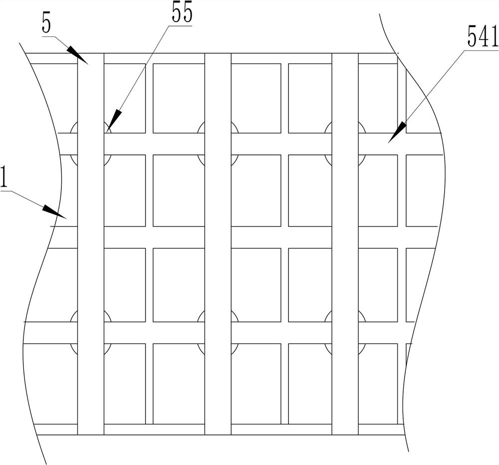
[0171] Such as Figure 13 As shown in part A in the middle, by adding a plurality of fixing pins 69 to connect the connecting cross bar 52 with the window sill rod 61, the whole door system is connected with the curtain wall system, which increases the shear resistance of the whole building. Due to the multiple fixing pins 69 is arranged inside the thermal insulation material, which will not produce cold and thermal bridges due to connection, and does not need to be broken bridges. While achieving the requirements of thermal insulation and low energy consumption, it has increased shear resistance compared to Example 1. The specifications and materials of the fixed pin 69 can refer to the connecting cross bar 52.

Embodiment 3

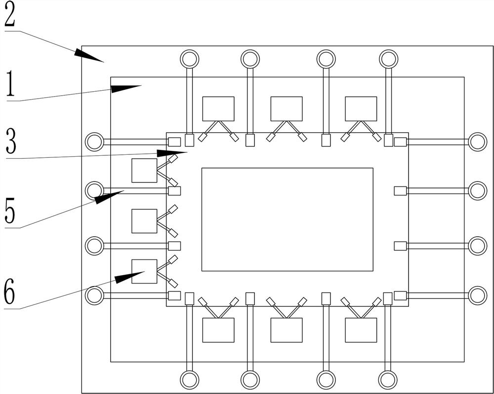
[0173] Such as Figure 13 In part B, Figure 14 As shown, the curtain wall system 6 includes an outer curtain wall system and an inner curtain wall system;

[0174] The inner curtain wall system is composed of a curtain wall structure connecting the prefabricated insulation board 1 and the main structure layer 3 of the concrete building from bottom to top; the curtain wall structure of the upper layer and the curtain wall structure of the lower layer are connected through a second connecting block 8 connections; the exterior curtain wall system includes a reinforced connector connecting the concrete fire protection shear protection layer 2 and the prefabricated insulation board 1; one end of the reinforced connector is connected to the window sill pole 61, and the other end is connected to the vertical Connect to pillar 51; Described reinforcing connector is reinforcing straight rod 66, by reinforcing straight rod 66, prefabricated insulation board 1 is connected with the con...

Embodiment 4

[0176] Such as Figure 13 , 15 As shown, the reinforcing connector can also be set as a reinforcing fork 67 arranged in the same form as the inner wire. The reinforcing fork 67 can be two forks or more than two forks that are evenly distributed in any direction in space. The reinforcing fork 67 Can be prefabricated in the prefabricated insulation board 1 in factory. The structure between the prefabricated insulation board 1 and the concrete fire protection shear protection layer 2 can form a triangular stable structure, which is beneficial to the lateral and horizontal force of the outer vertical pole 51 and the window sill pole 61, and is also conducive to the inclined force . Provide guarantee for the stability of the entire building.


PUM


Abstract

The invention discloses a core tube type broken bridge composite wall system for a low-energy-consumption building and a construction method. The system comprises a concrete fireproof shear protectionlayer, a prefabricated insulation board, and a floor core tube system. The core tube system comprises a concrete building main body structure layer, door type systems and curtain wall systems which are arranged in the concrete fireproof shear protection layer, the prefabricated insulation board and the concrete building main body structure layer. According to the core tube type broken bridge composite wall system for the low-energy-consumption building and the construction method, a door-type structure, a curtain wall structure and a building main body of a concrete shear wall structure are combined to form an outer wall broken bridge heat preservation system of a core tube type anti-seismic structure type, so that the earthquake resistance and other safety performance of the whole building are improved. Due to the fact that the concrete fireproof shear protection layer with a shear wall function is adopted, floor overhanging is not needed, heat preservation and bridge cutoff treatment are thoroughly achieved at the outer side end of a floor, and the building energy-saving effect is improved. The core tube type broken bridge composite wall system for the low-energy-consumption building is applied to the field of low-energy-consumption buildings with low floors, multiple floors and high floors.

Description

technical field [0001] The invention relates to the technical field of building thermal insulation wall engineering, in particular to a core tube type broken bridge composite wall system and construction method for low energy consumption buildings. Background technique [0002] Safety impact: The concrete fire protection layer, prefabricated insulation board, and shear wall joints of the main structural layer of the concrete building in the existing low-energy structural insulation integrated building technology are fragile, which can easily cause the concrete fire protection layer and insulation layer to fall off or crack. It causes a great safety hazard; because the joints are weak, the anti-seismic performance of the external wall insulation system is very poor. Once there is an earthquake, the entire concrete fire protection layer and insulation layer will fall off, causing greater damage to life and property. [0003] Impact on energy saving: The existing low-energy-con...

Claims


Application Information

Patent Timeline
IPC IPC(8): E04B2/00E04B1/34E04B1/80E04B1/94E04B1/98E04B2/88E04B1/38E04G21/14
CPCE04B1/34E04B1/38E04B1/80E04B1/941E04B1/98E04B2/00E04B2/88E04G21/14
Inventor 崔景新孙庆雷宫海军
Owner 崔景新
Why Eureka
Eureka Blog
Learn More