Propeller and aircraft

A technology of propulsion and burner, applied in the field of aircraft, can solve the problems of poor heat dissipation energy, high working temperature of combustion chamber and turbine area, and small space of central axis, so as to achieve large power output coverage, reduce connection difficulty, and layout difficulty reduced effect

Active Publication Date: 2021-03-12
邓云娣
View PDF13 Cites 4 Cited by
  • Summary
  • Abstract
  • Description
  • Claims
  • Application Information

AI Technical Summary

Problems solved by technology

In this traditional layout mode, a lot of equipment is arranged in the narrow space of the central axis. Due to the small space of the central axis and poor heat dissipation energy, the working temperature of the combustion chamber and the turbine area is very high. These equipment, especially the transmission shaft and lubrication system, which poses a great challenge
On the other hand, since the central axis occupies a larger projected area in the center of the windward side of the propeller, and the combustion chambers are arranged around the central axis to form an annular or ring-shaped combustion chamber with a large number of fuel injectors, these fuel injectors The nozzle or annular tube and the central shaft create a large resistance to the entire airflow path, reducing the efficiency of the propeller
Moreover, due to the limitations of the layout, the structure is very complicated, and the structural weight of the propeller is relatively large, which is not conducive to the increase of the thrust-to-weight ratio

Method used


Image

  • Propeller and aircraft
  • Propeller and aircraft
  • Propeller and aircraft

Examples


Embodiment 1

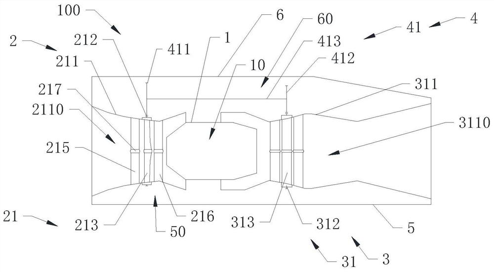
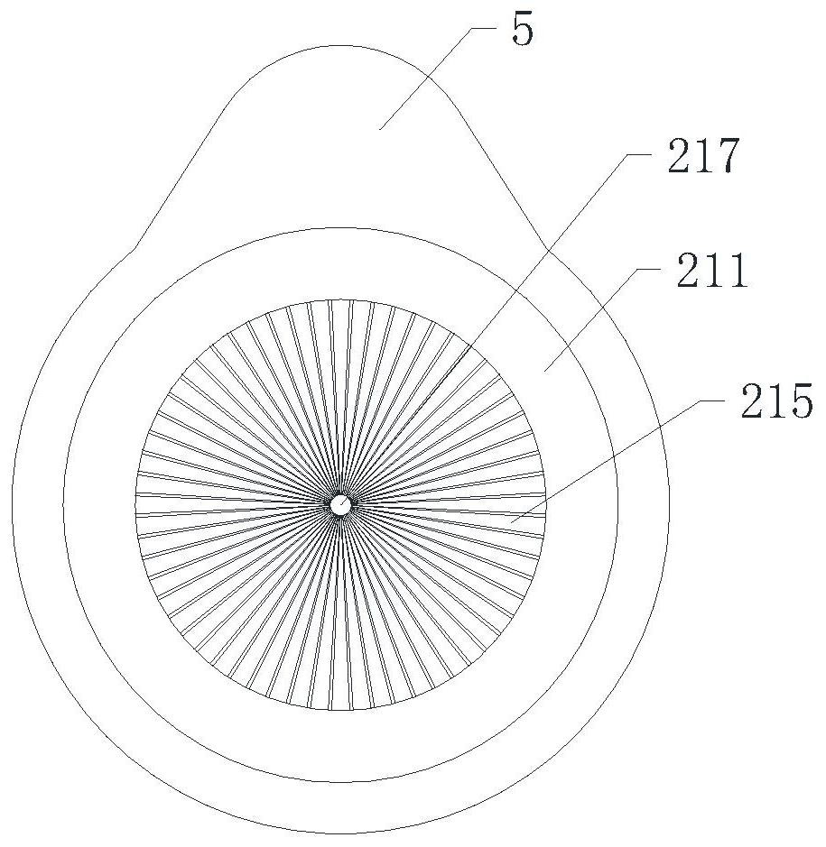
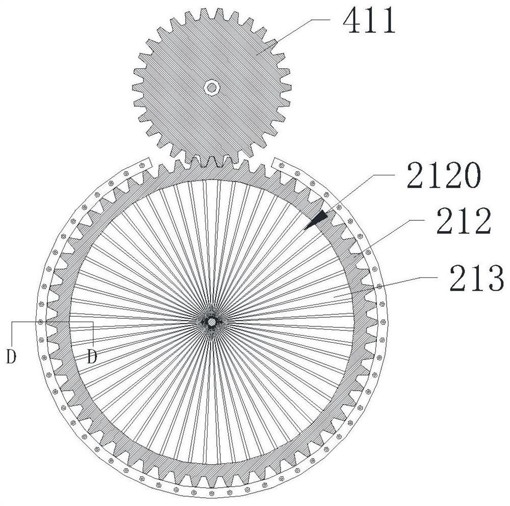
[0071] Reference manual attached Figure 1 to Figure 4 , the propeller 100 provided by the present invention is described. The propeller 100 uses shaftless blades instead of traditional shafted blades. The blade root is at the outer ring, and the root cross-sectional area and stiffness are greatly improved. When the compressor rotates at high speed, the huge centrifugal force generated by the blades generates pressure instead of pulling force at the blade root, which greatly reduces the difficulty of connecting the blade root and improves the fatigue performance at the blade root; the connecting sleeve can be installed at the central axis of the shaftless blade, Make the blades balance part of the centrifugal force in the form of tension between the blades, reduce the compressive stress at the root of the shaftless blade at the ring gear, and at the same time, the shaftless blades connected as a whole have higher stiffness in the airflow direction, so that the design and layout...

Embodiment 2

[0101] Reference manual attached Figure 5 , the second preferred embodiment of the propeller provided by the present invention is described, the structure of the propeller of the second preferred embodiment is basically the same as that of the first preferred embodiment, the difference is that in this In a preferred embodiment, the gas inlet mechanism 2 and the gas outlet mechanism 3 respectively have a multi-stage structure design.

[0102] Specifically, the gas inlet mechanism 2 includes a first air intake unit 221 , and the first air intake unit 221 includes more than one compressed air assembly 21 . Preferably, the first air intake unit 221 includes two compressed air assemblies 21 .

[0103] The gas discharge mechanism 3 includes a first exhaust unit 321 , and the first exhaust unit 321 includes more than one exhaust assembly 31 . Preferably, the first exhaust unit 321 includes one exhaust assembly 31 .

[0104] The transmission mechanism 4 includes a first transmissi...

Embodiment 3

[0120] Reference manual attached Figure 6A with Figure 6B , the third preferred embodiment of the propeller provided by the present invention is described, the structure of the propeller of the third preferred embodiment is substantially the same as that of the second preferred embodiment above, the difference is that in the third preferred In an embodiment, the gas discharge mechanism 3 further includes a power output unit 324, the gas discharged from the combustion chamber 10 can drive the power output unit 321 to work, and the power generated by the power output unit 324 can be transmitted to the outside of the thruster.

[0121] Specifically, the power output unit 324 includes more than one exhaust assembly 31, a power output shaft 324, and a power output gear 3242, wherein the power output gear 3242 is installed on one end of the power output shaft 3241, and the The power output gear 3242 meshes with the exhaust gear 312 of the exhaust assembly 31 of the power output ...


PUM


Abstract

The invention discloses a propeller and an aircraft. The propeller comprises a burner, a gas entering mechanism, a gas discharging mechanism, a transmission mechanism and a shell, wherein the burner is provided with a burning chamber; the gas entering mechanism comprises a pressing assembly which comprises a pressing shell, a pressing gear and a pressing blade; the pressing shell is provided withan air inlet runner and a pressing gear chamber; the pressing gear is provided with a pressing hollow cavity; the gas discharging mechanism comprises an exhausting assembly which comprises an exhausting shell, an exhausting gear and an exhausting blade; the exhausting shell is provided with an exhausting runner and the exhausting gear cavity; the exhausting gear is provided with an exhausting hollow cavity; the transmission mechanism comprises a transmission assembly which comprises an air inlet transmission gear, an exhausting transmission gear and a transmission connecting part; and the shell is provided with a mounting cavity, and the burner, the gas entering mechanism, the gas discharging mechanism and the transmission mechanism are separately mounted in the mounting cavity of the shell. The propeller is simple and compact in structure and space-saving.

Description

technical field [0001] The invention relates to the field of aircraft, and further relates to a propeller and an aircraft. Background technique [0002] After nearly 80 years of development, axial-flow propellers have developed propellers including turbojet, turbofan (including small bypass ratio and high bypass ratio), turboprop, paddle fan, turboshaft and gas turbine, but they have always been It does not get rid of the traditional central shaft transmission mode in which the belt drive shaft is in the middle and the blades are arranged around. In this traditional layout mode, a lot of equipment is arranged in the narrow space of the central axis. Due to the small space of the central axis and poor heat dissipation energy, the working temperature of the combustion chamber and the turbine area is very high. These equipment, especially the transmission shaft and lubrication system poses great challenges. On the other hand, since the central axis occupies a larger projected...

Claims


Application Information

Patent Timeline
Patent Type & Authority Applications(China)
IPC IPC(8): F02K3/00F02C7/36B64D33/02B64D33/04
CPCF02K3/00F02C7/36B64D33/02B64D33/04F04D19/026F04D19/00F04D25/02F02K3/06F01D5/03F02C6/20F02C6/206F05D2260/4031F05D2260/53F05D2260/532
Inventor 邓云娣
Owner 邓云娣
Why Eureka
Try Eureka