Photovoltaic power station wiring method and device

A photovoltaic power station and wiring method technology, applied in electrical digital data processing, structured data retrieval, instruments, etc., can solve problems such as low efficiency and affect the progress of photovoltaic power station projects, achieve a wide range of application scenarios, improve wiring design efficiency, and wiring flexible effect

Pending Publication Date: 2021-03-12
HEFEI SUNGROW RENEWABLE ENERGY SCI & TECH CO LTD
View PDF9 Cites 1 Cited by
  • Summary
  • Abstract
  • Description
  • Claims
  • Application Information

AI Technical Summary

Problems solved by technology

However, the efficiency of manual design is extremely low, which greatly affects the project progress of photovoltaic power plants

Method used


Image

  • Photovoltaic power station wiring method and device
  • Photovoltaic power station wiring method and device
  • Photovoltaic power station wiring method and device

Examples


Embodiment 1

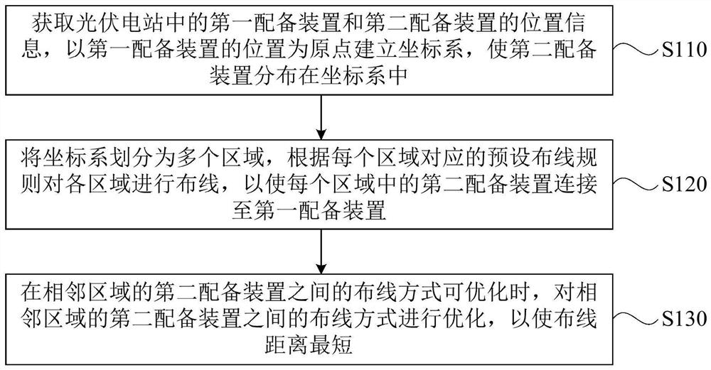
[0055] figure 1 It is a schematic flow chart of a wiring method for a photovoltaic power station provided by an embodiment of the present invention. This embodiment is applicable to the case of wiring equipment in a photovoltaic power station. This method can be executed by a wiring device for a photovoltaic power station. The device can use software and / or hardware, the device can be configured in electronic equipment, such as a server or a terminal device, and a typical terminal device includes a mobile terminal, specifically a mobile phone, a computer, or a tablet computer.

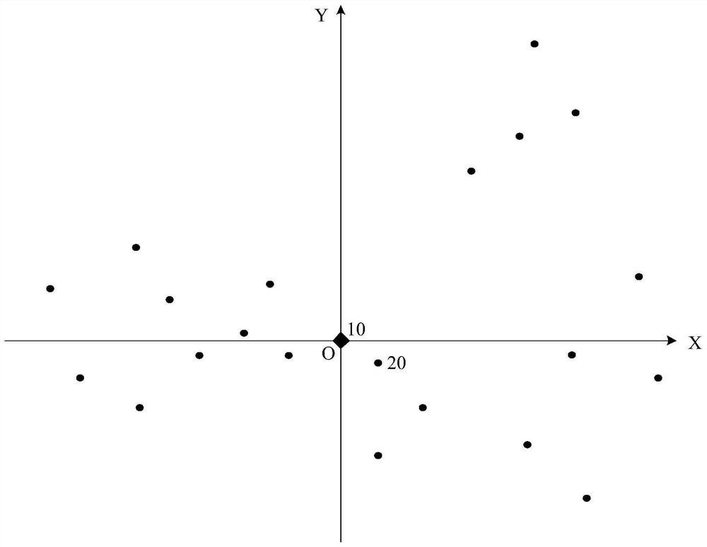
[0056] figure 2 It is a schematic diagram of the distribution position of the equipped devices of a photovoltaic power station provided by the embodiment of the present invention, figure 2 It schematically shows a distribution situation of the first equipment device and the second equipment device in the photovoltaic power station provided by the embodiment of the present invention, as shown in fi...

specific Embodiment

[0134] Figure 7 It is a schematic flow chart of another wiring method for a photovoltaic power station provided by an embodiment of the present invention. This embodiment further optimizes the above wiring method for a photovoltaic power station. In this embodiment, the photovoltaic power station is still a centralized photovoltaic power station, and the wiring between the box-type transformer and the combiner box is taken as an example for schematic illustration. Such as Figure 7 As shown, the method may specifically include:

[0135] S610. Establish a coordinate system with the box as the origin.

[0136] S620. Obtain a user-defined parameter.

[0137] Wherein, the custom parameters include a preset rotation angle.

[0138] S630. Divide the coordinate system into multiple regions according to the preset rotation angle, and acquire the coordinates of the combiner box in each region.

[0139] S640. Wiring the combiner boxes in each area.

[0140] S650. Optimizing the w...

Embodiment 2

[0144] Figure 8 It is a schematic diagram of the module structure of a photovoltaic power plant wiring device provided by the embodiment of the present invention. This embodiment is applicable to the wiring of the equipped devices in the photovoltaic power plant. The photovoltaic power station wiring device provided by the embodiment of the present invention can execute the photovoltaic power station wiring method provided by any embodiment of the present invention, and has corresponding functional modules and beneficial effects for executing the method. The photovoltaic power station includes a first equipped device and a plurality of second equipped devices; correspondingly, as Figure 8 As shown, the device specifically includes a coordinate system establishment module 710, a wiring module 720 and a wiring optimization module 730, wherein:

[0145] The coordinate system establishment module 710 is used to obtain the position information of the first equipped device and th...


PUM


Abstract

The embodiment of the invention discloses a photovoltaic power station wiring method and device. The photovoltaic power station comprises a first equipping device and a plurality of second equipping devices. The photovoltaic power station wiring method comprises the steps of obtaining position information of a first configuration device and a second configuration device in a photovoltaic power station, establishing a coordinate system by taking the position of the first configuration device as an original point, and enabling the second configuration device to be distributed in the coordinate system; dividing the coordinate system into a plurality of regions, and performing wiring on each region according to a preset wiring rule corresponding to each region, so that the second equipping device in each region is connected to the first equipping device; and when the wiring mode between the second equipping devices in the adjacent area can be optimized, the wiring mode between the second equipping devices in the adjacent area being optimized, so that the wiring distance is the shortest. Compared with the prior art, the technical scheme of the invention is wider in application scene, facilitates the improvement of the wiring design efficiency of the photovoltaic power station, and reduces the wiring and construction cost.

Description

technical field [0001] Embodiments of the present invention relate to the technical field of photovoltaic power plants, and in particular to a wiring method and device for photovoltaic power plants. Background technique [0002] Photovoltaic power plants can be divided into centralized photovoltaic power plants and string photovoltaic power plants. For centralized photovoltaic power plants, there are many photovoltaic modules collected by the centralized inverter, and a combiner box is generally arranged between the photovoltaic modules and the centralized inverter; There are few photovoltaic modules, and generally photovoltaic modules are directly connected to the inverter. There is no exact optimal solution for the wiring between the combiner box and the inverter in the centralized photovoltaic power station, and the wiring between the inverter and the box-type transformer in the string photovoltaic power station, especially for mountainous power stations. On-site constr...

Claims


Application Information

Patent Timeline
Patent Type & Authority Applications(China)
IPC IPC(8): G06F30/20G06F16/29G06F16/2455G06Q50/06
CPCG06F30/20G06F16/29G06F16/24564G06Q50/06Y04S10/50Y02E40/70Y02D10/00
Inventor 杨雷王忠陆克华周辉宋平
Owner HEFEI SUNGROW RENEWABLE ENERGY SCI & TECH CO LTD
Why Eureka
Try Eureka