A clamping circuit of an active clamp flyback converter and its control method

A technology of flyback converter and clamping circuit, which is applied in the direction of control/regulation system, conversion of DC power input to DC power output, instruments, etc. The problem of low efficiency of the device can be solved, and the effect of solving the change of resonance period, improving efficiency and improving EMI

Active Publication Date: 2022-03-18
MORNSUN GUANGZHOU SCI & TECH
View PDF7 Cites 0 Cited by
  • Summary
  • Abstract
  • Description
  • Claims
  • Application Information

AI Technical Summary

Problems solved by technology

It can be seen from the actual test waveform that when the drive of the main switching tube is turned off, the leakage inductance and the clamping capacitor start to resonate through the body diode of the clamping switch tube. Due to the poor reverse recovery characteristics of the body diode, after the resonance current crosses zero, Due to the existence of reverse recovery of the body diode, there is a negative current in the discharge of the resonant capacitor, which extracts the junction capacitance charge of the main switch tube, causing the voltage of the main switch tube Vds1 to drop. When the reverse recovery of the body diode of the clamp switch tube ends, the negative current immediately At this time, the Vds voltage of the main switching tube starts to rise again. If the excitation current crosses zero during the rising process, it will cause the resonance cycle to change. The final result makes the clamping switch tube unable to achieve QR (quasi-resonant) conduction. pass, the temperature rise of the clamp switch tube becomes larger, and the efficiency of the entire converter is low

Method used


Image

  • A clamping circuit of an active clamp flyback converter and its control method
  • A clamping circuit of an active clamp flyback converter and its control method
  • A clamping circuit of an active clamp flyback converter and its control method

Examples


no. 1 example

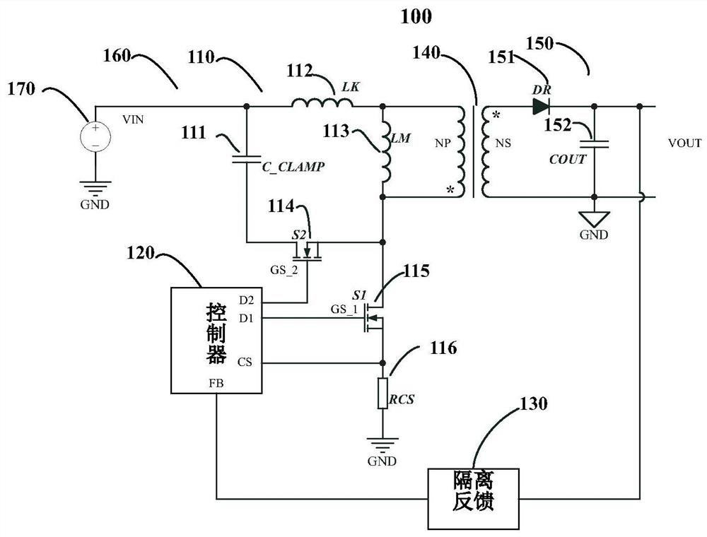
[0025] In this example, if Figure 4 shown. The active clamp flyback converter includes a main switching tube 401, a clamping switching tube 402, a low voltage switching tube 403, a clamping capacitor 404 and a transformer 405. The drain of the main switching tube 401 is connected to the source of the clamping switching tube 402 and The opposite end of the primary winding of the transformer 405, the source of the main switching tube 401 is grounded, the drain of the clamping switching tube 402 is connected to the source of the low-voltage switching tube 403, and the drain of the low-voltage switching tube 403 is connected to one end of the clamping capacitor 404, The other end of the clamping capacitor 404 is connected to the same-named end of the primary winding of the transformer 405, where LK is the leakage inductance, and Lm is the excitation inductance.

[0026] This embodiment takes advantage of the good body diode reverse recovery characteristics of the low-voltage swi...

no. 2 example

[0031] In this example, if Figure 6 shown. The active clamp flyback converter includes a main switching tube 501, a clamping switching tube 502, a first diode 503, a second diode 504, a clamping capacitor 505 and a transformer 506, and the drain of the main switching tube 501 is connected to The source of the clamp switch tube 502 is connected to the opposite end of the primary winding of the transformer 506, the source of the main switch tube 501 is grounded, the drain of the clamp switch tube 502 is connected to the cathode of the first diode 503, and the first diode The anode of 503 is connected to one end of the clamping capacitor 505, and the other end of the clamping capacitor 505 is connected to the end of the primary winding of the transformer 506; the second diode 504 is connected in antiparallel between the first diode 503 and the clamping switch tube 502 The two ends of the formed series branch, that is, the cathode of the second diode 504 is connected to the anod...


PUM


Abstract

The invention discloses a clamp circuit of an active clamp flyback converter and a control method thereof. By connecting a switch unit with good reverse recovery characteristics in series in a clamp capacitor discharge circuit, when the main switch tube is turned off, when the main switch tube is turned off, After the resonant current is reduced to zero, the resonant current only generates a negative current and the switch unit can be turned off, so as to prevent the energy stored in the clamping capacitor from being accidentally released during the turn-off of the main switch. It can improve the efficiency of the flyback converter and improve the EMI of the flyback converter by solving the problem of the resonant period change caused by the recovery.

Description

technical field [0001] The invention relates to the field of switching converters, in particular to a clamp circuit of an active clamp flyback converter and a control method thereof. Background technique [0002] Flyback converters are widely used in small and medium power switching power supplies because of their low cost and simple topology. In the actual working process, due to the existence of the leakage inductance of the flyback converter, the energy of the primary side cannot be completely transferred to the secondary side, and the resonance between the leakage inductance energy left on the primary side and the junction capacitance of the MOS tube causes the drain of the main switch tube Generate high frequency voltage spikes. In order to reduce the voltage stress of the switch tube when making products, it is common practice to add suitable snubber circuits. Common snubber circuits include RCD snubber circuits, LCD snubber circuits and active clamp circuits. Among ...

Claims


Application Information

Patent Timeline
Patent Type & Authority Patents(China)
IPC IPC(8): H02M1/32H02M3/335H02M1/44
CPCH02M1/32H02M3/3353H02M1/44
Inventor 王海洲袁源
Owner MORNSUN GUANGZHOU SCI & TECH
Why Eureka
Try Eureka