
Ceramic-based annular flame tube

A ceramic-based, flame tube technology, applied in the direction of combustion methods, combustion chambers, combustion equipment, etc., to achieve the effects of reducing exhaust emissions, improving thermal efficiency, and increasing working temperature

Inactive Publication Date: 2021-03-16
NANJING UNIV OF AERONAUTICS & ASTRONAUTICS
View PDF7 Cites 5 Cited by
  • Summary
  • Abstract
  • Description
  • Claims
  • Application Information

AI Technical Summary

Problems solved by technology

This poses a severe challenge to the material selection and design of the aero-engine combustor flame tube

Method used


Image

  • Ceramic-based annular flame tube
  • Ceramic-based annular flame tube
  • Ceramic-based annular flame tube

Examples


example

[0053] The maximum thrust state on the ground is selected as the working condition for simulation. Working condition parameters are shown in Table 1.

[0054] Table 1 Combustion chamber working condition parameters

[0055]

[0056] In order to simplify the calculation and design quickly, without affecting the reliability of the design, the following assumptions are made:

[0057] 1) Look at the air as an ideal gas, and use the ideal gas state equation to calculate the density and pressure in the calculation;

[0058] 2) In the calculation, the expansion process is regarded as adiabatic, so the total temperature remains unchanged;

[0059] The simulation results are as follows:

[0060] Such as Figure 12 As shown, due to the existence of the recirculation zone, there will be a region in the flow field where the gas velocity is exactly equal to the flame propagation velocity, so that the ignition source exists stably. The combustion in the flame tube is mainly concentr...


PUM

PropertyMeasurementUnit
combustion efficiencyaaaaaaaaaa

Abstract

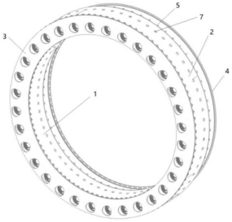
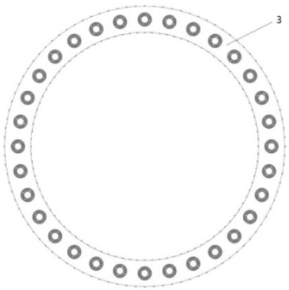
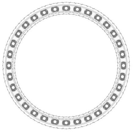
The invention relates to a ceramic-based annular flame tube. The ceramic-based annular flame tube comprises a tube main body, a rear support and a front end cover, wherein the tube main body and the rear support are made of integrally-woven SiCf / SiCm materials, and the front end cover is made of high-temperature alloy. According to the ceramic-based annular flame tube, ellipse-like inclined holesare designed to be formed in the tube wall of the flame tube, and the circumferential inclination angle is set to achieve the optimal cooling effect; in order to solve the problem of thermal mismatchof connection between parts made of different materials, thermal mismatch compensation slits are formed in a head joint and the rear support; and the flame tube made of a ceramic matrix composite is mainly applied to aero-engines and has the characteristics of being light in weight, high in using temperature, good in cooling effect, convenient to machine and the like.

Description

technical field [0001] The invention relates to the field of aero-engine structural design, in particular to a ceramic-based annular flame cylinder. Background technique [0002] The flame tube is an important core component of an aero-engine, and it is one of the parts with the highest temperature in the engine. The performance and reliability of the flame tube largely determines the performance and reliability of the engine. In the flame cylinder, the chemical energy in the fuel is converted into heat energy, which heats the high-pressure air after the compressor pressurization to the temperature that the turbine can withstand, so that it can enter the turbine to do work. Since the flame tube is a perforated and thin-walled structure, there are many cooling air film holes and mixing holes with different apertures on the tube wall, resulting in a large temperature gradient in the temperature distribution of the flame tube, which is prone to stress concentration. The flame...

Claims


Application Information

Patent Timeline
Patent Type & Authority Applications(China)
IPC IPC(8): F23R3/44
CPCF23R3/44
Inventor 宋迎东陈正扬高希光张盛于国强
Owner NANJING UNIV OF AERONAUTICS & ASTRONAUTICS
Learn More