
System and method for machining microcircuit on surface of carbon-based polymer by using femtosecond laser

A carbon-based polymer and femtosecond laser technology, applied in the field of femtosecond laser applications, can solve problems such as difficult to meet the needs of microcircuits, reduce the capacitance of supercapacitors, and affect the integration of microcircuits, so as to reduce the risk of conduction failure , Edge burr suppression, electrode gap reduction effect

Inactive Publication Date: 2021-03-19
TSINGHUA UNIV +1
View PDF7 Cites 2 Cited by
  • Summary
  • Abstract
  • Description
  • Claims
  • Application Information

AI Technical Summary

Problems solved by technology

Components processed by oscillation-level laser direct writing may be connected by burrs, resulting in short circuit of components and failure to work normally
In order to prevent burrs from making the two components or electrodes fail, we can only increase the distance between the components or electrodes, but this will affect the integration of the microcircuit, reduce the capacitance of the supercapacitor, and it is difficult to meet the expected use requirements of the microcircuit

Method used


Image

  • System and method for machining microcircuit on surface of carbon-based polymer by using femtosecond laser
  • System and method for machining microcircuit on surface of carbon-based polymer by using femtosecond laser
  • System and method for machining microcircuit on surface of carbon-based polymer by using femtosecond laser

Examples


Embodiment 1

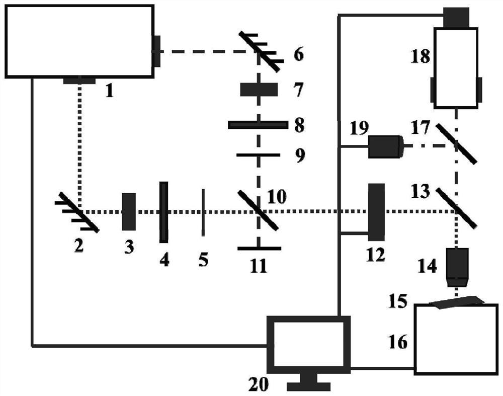
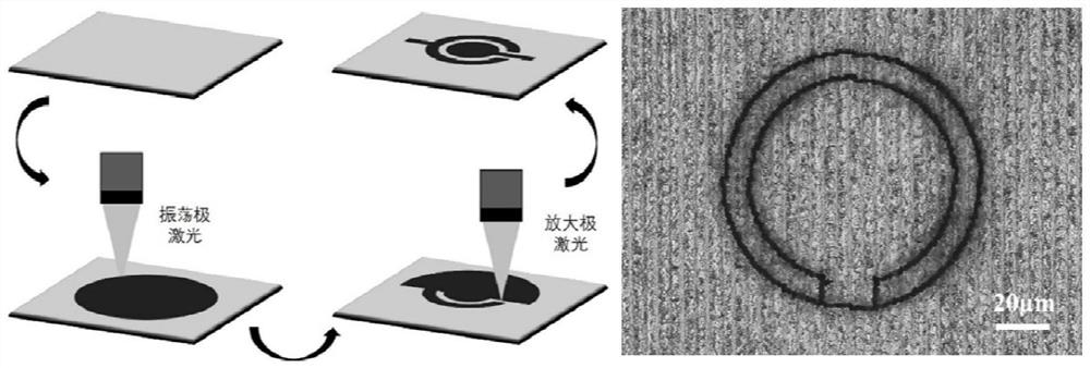
[0033] The circular supercapacitor electrode is machined on the surface of the carbon-based polymer, first opening the femtosecond laser 1 generates femtosecond laser light, and adjusts the oscillation grade laser spot diameter of 5 mm by the first dripper 3, and the first attenuation piece 4 regulates the oscillation level laser power. 20MW, adjusting the extensive laser spot diameter of 5 mm by the second phenostot 7 adjustment, the second attenuation piece 8 adjusts the magnification laser flux is 1.2J / cm 2 The height of the adjustment changing table 16 causes femtosecond laser focusing on the surface of the carbon-based polymer sample 15, and the imaging system is adjusted to clearly imaging. The translational speed of the pan 16 is set to 1000 μm / s, and the optical path of the amplifying stage laser is blocked using the second retaining plate 9, and the control of the electric control shutter 12 outputs the oscillation level laser, and the translation path is designed acc...

Embodiment 2

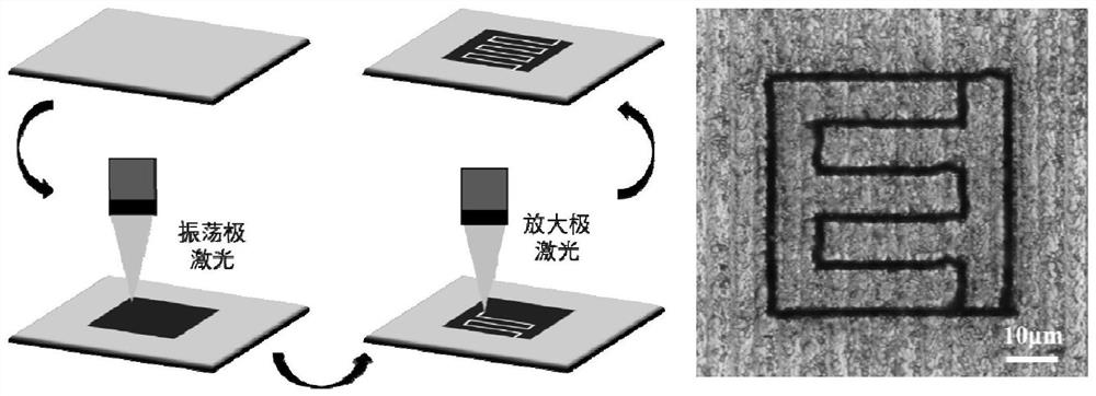
[0036] In the surface of the carbon-based polymer, a fork-finger supercapacitor electrode is first opened, and the femtosecond laser 1 generates femtosecond laser, and the oscillation grade laser spot diameter is 5mm by the first phenostap 3, and the first attenuation piece 4 regulates the oscillation level laser power. 20MW, adjusting the diameter of the laser spot in the diameter of 5 mm, the second attenuation piece 8 adjusts the magnification of 1.2J / cm 2 The height of the adjustment changing table 16 causes femtosecond laser focusing on the surface of the carbon-based polymer sample 15, and the imaging system is adjusted to clearly imaging. The translational speed of the translational stage 16 is 1000 μm / s, and the optical path of the amplified stage laser is blocked using the second retaining plate 9, and the control shutter 12 outputs the oscillation level laser, and the overall outer contour of the fork finger electrode is translated. The path such that the laser focus...

Embodiment 3

[0039] The micro-parallel resistance is machined on the surface of the carbon-based polymer, first opening the femtosecond laser 1 to generate femtosecond lasers, and adjust the oscillation grade laser spot diameter of 5 mm by the first phenadene 3, and the first attenuation piece 4 adjusts the oscillation level laser power of 20 mW. Adjusting the diameter of the amplification of the laser spot in the diameter of 5 mm, the second attenuation piece 8 adjusts the magnification of 1.2J / cm 2 The height of the adjustment changing table 16 causes femtosecond laser focusing on the surface of the carbon-based polymer sample 15, and the imaging system is adjusted to clearly imaging. The translational speed of the changing table 16 is 1000 μm / s, and the optical path of the amplifying stage laser is blocked using the second retaining plate 9, and the control shutter 12 outputs the oscillation level laser, and the translation path is designed according to the overall outer contour of the ...


PUM

PropertyMeasurementUnit
diameteraaaaaaaaaa

Abstract

The invention provides a system and a method for machining a microcircuit on the surface of a carbon-based polymer by using femtosecond laser, and belongs to the technical field of femtosecond laser application. Different light emitting modes of a femtosecond laser are combined and used for machining, the carbon-based polymer is carbonized by utilizing an oscillation-stage laser to obtain a conductive carbonized layer, and then the redundant carbonized layer is accurately removed by utilizing an amplification-stage laser, so that a circuit element is machined. By utilizing the system and the method provided by the invention, the carbon-based microcircuit can be rapidly and accurately machined on the surface of the carbon-based polymer, and a flexible circuit can be successfully prepared when the flexible carbon-based polymer is used. The system has the advantages of being convenient to adjust, flexible in switching and high in adaptability, by means of the method provided by the invention, the defects of carbonization and direct writing machining of the oscillation-stage laser can be overcome, burrs between the machined microcircuits are effectively restrained, the distance betweenthe circuit elements is shortened, the risk of short-circuit faults of the microcircuits is reduced, miniaturization of the circuit is facilitated, and the integration level of the circuit is improved. The method has the advantages of high machining precision, multiple machinable materials, flexible shapes of machinable circuit elements and the like, and a feasible scheme is provided for preparing the carbon-based flexible microcircuit.

Description

Technical field [0001] The present invention belongs to the field of femtosecond laser applications, and more particularly to systems and methods for processing microcircuits using femtosecond laser surfaces in a carbon-based polymer. Background technique [0002] The flexible circuit is a special circuit formed on the flexible substrate, which has a wide range of bending, light weight, small thickness, and wearable, and the carbon-based polymer often serves as a flexible circuit board. In the conventional processing of flexible circuits, the etching method is not conducive to environmental protection and sustainable development, and the bonding can be bonded to the board. It is a method for preparing a flexible circuit using a laser on the surface of the flexible substrate. [0003] The femtosecond laser has an oscillation level and an enlarged two output modes. The peak power of the oscillating grade laser is low, but the repetition frequency is very high, and the material can ...

Claims


Application Information

Patent Timeline
Patent Type & Authority Applications(China)
IPC IPC(8): B23K26/36B23K26/402B23K26/70
CPCB23K26/36B23K26/402B23K26/702
Inventor 姜澜闫剑锋郭恒黄辰潇
Owner TSINGHUA UNIV
Learn More