Base part machining method and tool

A part processing and base technology, applied in the field of mechanical processing, can solve the problems of crushing, deformation, easy deformation, etc., and achieve the effect of eliminating deformation, eliminating convex and concave deformation, and improving cutting performance

Inactive Publication Date: 2021-03-23
云南航天红云机械有限公司
View PDF0 Cites 0 Cited by
  • Summary
  • Abstract
  • Description
  • Claims
  • Application Information

AI Technical Summary

Problems solved by technology

[0003] The object of the present invention is to provide a method for processing base parts and its tooling. The method adopts vacuum thermal processing and cryogenic process to remove the processing stress of parts under a certain degree of vacuum, and the cryogenic process continues to eliminate processing stress. Stress, use the grinding method to finish the base surface of the part, make a forming measuring tool to ensure the measurement accuracy and efficiency of the part and the gyro body, and ensure the processing dimensional accuracy requirements of the part and the accuracy of the measurement. The grinding fixture used in this method is effective It prevents the difficulty that the part material cannot be sucked, avoids the crushing and deformation of the part clamping, solves the problem that the base part is easily deformed during processing due to thin wall and poor rigidity, and realizes the rapid clamping of the part; at the same time, After the parts are processed, the special measuring tool is used to insert the pin shaft directly into the processed hole, and can be measured directly on the base, which avoids waiting in the three-coordinate measuring instrument and cumbersome point measurement, thereby improving the measurement of the base parts Efficiency and Position Dimensional Accuracy

Method used


Image

  • Base part machining method and tool
  • Base part machining method and tool
  • Base part machining method and tool

Examples


Embodiment 1

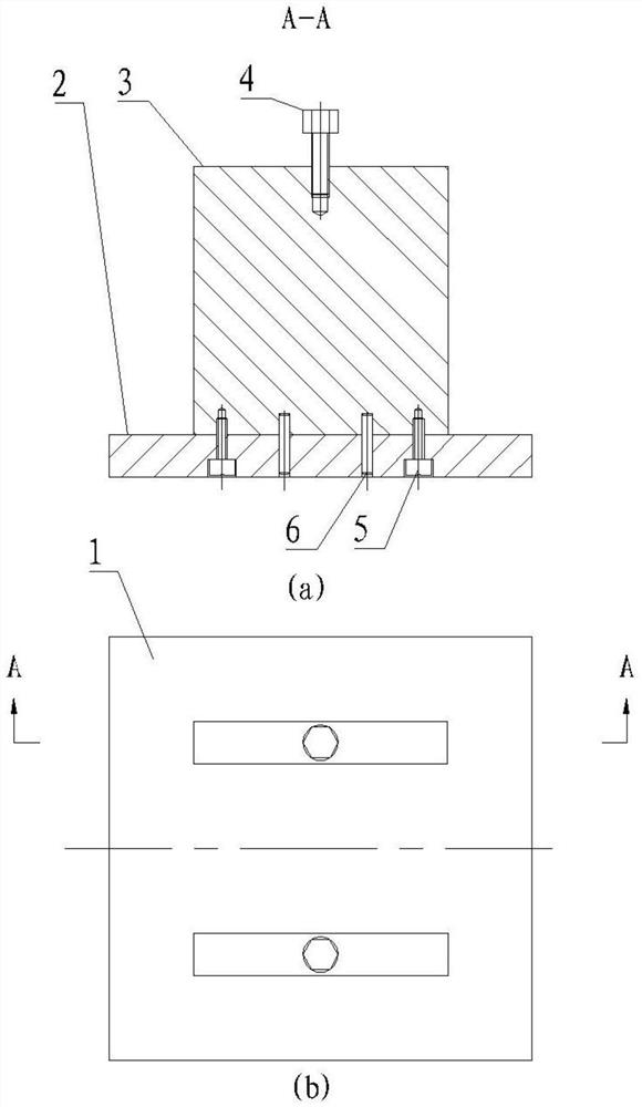
[0036] A method for processing base parts, comprising the steps of:

[0037] Step 1) By controlling the machine tool speed, cutting depth and tool feed rate of the machine tool, the base parts are roughly machined in multiple feeds to remove large machining allowances;

[0038] Step 2) After rough machining, carry out the first vacuum heat treatment;

[0039] Step 3) For the base parts after the first vacuum heat treatment in step 2), the faceplate of the machine tool is fixed and aligned, and the base is semi-finished in multiple feeds by controlling the machine speed, cutting depth and tool feed rate of the machine tool Parts, semi-finishing base parts in multiple feeds;

[0040] Step 4) After semi-finishing, then carry out cryogenic heat treatment to further eliminate processing stress;

[0041]Step 5) Finishing the base part after the cryogenic heat treatment, adopting a grinding fixture for clamping and positioning, and completing the dimensional requirements for the fi...

Embodiment 2

[0045] A method for machining a base part, characterized by:

[0046] Step 1) First, use the three-jaw chuck of the machine tool to clamp the blank of the part. Under the conditions of the machine tool speed of 350-700rmin, the cutting depth of 2mm, and the feed rate of 0.5-0.25mm / r, the rough machining is divided into multiple feeds Base parts, remove large machining allowances;

[0047] Step 2) After rough machining, the vacuum is 6×10 -2 Pa, the temperature is 500±10°C, and the time is 3±0.1 hours, the hanging type is used to make the parts fully heated and evenly in the vacuum furnace, and the first vacuum heat treatment is carried out; the lattice structure is refined to prevent titanium Alloy materials react strongly with oxygen, nitrogen, and hydrogen in the atmosphere at high temperatures, forming hard and brittle layers such as TiO2, TiN, and TiH, which cause local stress concentration on the machined surface layer, reduce fatigue strength, and aggravate tool wear. ...

Embodiment 3

[0062] On the basis of Example 2, the invented measuring tool is used to directly measure the processing size after the parts are finished.

[0063] Such as Figure 8 As shown, the measuring tool includes a body 17, a shaft sleeve 18 and a pin shaft 19 with reticulated texture;

[0064] Such as Figure 9 As shown, the body 17 includes a third positioning surface 20, a bushing hole 21, a weight reduction hole 22, and a fourth positioning surface 23; Parallel, the lightening hole 22 is located at the center of the body 17, and the bushing holes 21 are distributed in a certain position on the pitch circle of the body 17 according to the technical requirements of the parts.

[0065] Such as Figure 10 As shown, the shaft sleeve 18 includes a fifth chamfer 24, a sixth chamfer 25, a matching cylinder 26, a seventh chamfer 27, an eighth chamfer 28, and a pin positioning hole 29; The sixth chamfer 25 and the seventh chamfer 27 and the eighth chamfer 28 are distributed at both ends...


PUM


Abstract

The invention relates to a base part machining method and clamp. The method comprises the following steps: (1) roughly machining a base part in multiple feeding amounts, and removing large machining allowance; (2) carrying out first vacuum heat treatment; (3) fixing and aligning a machine tool faceplate, and carrying out semi-finishing on the base part in multiple feeding amounts by controlling the rotating speed, the cutting depth and the feeding amount of a machine tool; (4) carrying out second-time deep cooling and heating treatment; (5) carrying out clamping and positioning by adopting a grinding clamp, and then the size requirement for finishing of the base part is met through a grinding machining method; (6) placing the processed base part connected with a gyroscope body on a specialmeasuring tool to measure the size and the position of holes, and judging whether the size and the position of the holes meet technical requirements or not; and (7) if the measurement shows that thetechnical requirements are not met, carrying out finishing on the location degree and the size of the holes connected with a gyro frame, and returning to the step (6) after finishing, and if the measurement shows that the technical requirements are met, turning to the next procedure. According to the method, the machining precision is guaranteed, the pressure damage and deformation of the part areprevented, the machining and measuring efficiency is improved, and the cost is saved.

Description

technical field [0001] The invention relates to a part processing method, in particular to a method for processing base parts and tooling thereof. It belongs to the field of mechanical processing. Background technique [0002] At present, the base parts made of titanium alloy materials are relatively difficult to process. Due to thin walls and poor rigidity, they are easy to deform during processing. The wall thickness is 1.5mm, and the parts are irregular shapes. mm, the positioning outer circle of the part is φ239f7, the size of the 17 holes connecting the end face of the positioning outer circle and the gyro body is φ3.5H6 and the position tolerance is ±3', the verticality is 0.02mm, and the flatness is 0.02mm, especially in cutting processing When the outer circle of the part positioning is φ239f7, due to the deformation of the base surface, the size of the processing surface of the part expands outward, and vibration occurs to produce convex and concave distortion defo...

Claims


Application Information

Patent Timeline
Patent Type & Authority Applications(China)
IPC IPC(8): B23P15/00
CPCB23P15/00
Inventor 瞿生昆蒲兴平杨宇洲李建良张利军
Owner 云南航天红云机械有限公司
Why Eureka
Try Eureka